


Special offers from our partners!

Find Replacement BBQ Parts for 20,308 Models. Repair your BBQ today.

www.desatech.com
105116-01D 9
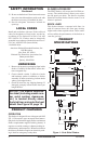
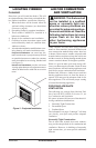
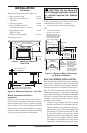
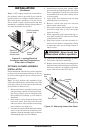
Figure 5 - Minimum Clearance -
Front View
42" Min.
0" to Wood Floor
8" Min.
0" Min. Clearance to
Upper Frame/Wallboard
Ceiling
4" Min. from the Perpendicular
Side Wall to the Edge of Facial
1/2" Min. Clearance
to Combustibles
44
1
/
4
"
24"
Figure 6 - Minimum Clearance - Top View
Minimum clearances to combustibles are:
• Sides of outer casing 0" min.
• Drywall to sides and top of 0" min.
front face
• Ceiling to opening 42' min.
• Floor (see Minimum Wall 0" min.
and Ceiling Clearances, note C)
• Perpendicular walls 4' min.
Right and Left
• Distance to Facing Walls 36" min.
See Figures 5 and 6.
INSTALLATION
Continued
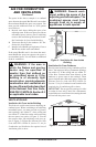
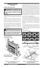
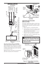
Mantel Clearances for Built-In
Installation
If placing custom mantel above built-in rebox,
you must meet the minimum allowable clearance
between mantel shelf and top of rebox opening
shown in Figure 7. These are the minimum allowable
mantel clearances for a safe installation. Use larger
clearances wherever possible to minimize the heating
of objects and materials placed on the mantel.
CAUTION: Do not allow the
vent-free gas log heater to touch
or extend beyond the rebox
screen.
If your installation does not meet the above mini-
mum clearances in Figure 7, you must:
• raise the mantel to an acceptable height,
OR
• remove the mantel.
Figure 7 - Minimum Mantel Clearances
for Built-In Installation
Supplied
Firebox Hoods
Must Be Used
at All Times
Wire-mesh
Screen
Firebox Top
Mantel Shelf
3"
6"
9
1
/
4
"
Combustible
Material 1
1
/
2
"
Max Thickness
Note: All vertical
measurements are
from top of fireplace
hood to bottom of
mantel shelf. These
minimum clearances
replace any other
recommended
clearances supplied
with your ANS Z21.11.2
approved gas logs.
Wall board or facing material
(above firebox) may be of
combustible material, including
decorative mantel ornaments
or other similar projections
off of the facing material.
Top Frame
(Combustible Material)
12"
15"
18"
Note: Do not
cover louver
openings.
7" Min.
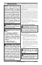
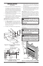
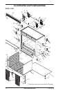
BUILT-IN FIREBOX INSTALLATION
Built-in installation of this rebox involves installing
rebox into a framed-in enclosure. This makes the
front of rebox ush with wall. Optional perimeter
brass trim accessories are available (see Accessories,
page 18). The brass trim will extend past sides of
rebox approximately 1/2". This will cover the rough
edges of the wall opening. If installing a mantel above
the rebox, you must follow the clearances shown
in Figure 7. Follow the instructions below to install
the rebox in this manner.
1. Frame in rough opening. The rebox framing
should be constructed of 2 x 4 lumber or heavier.
Construct framing using dimensions shown in
Figure 8 and 9, page 10. It is recommended that
the framing be constructed rst and the unit
be placed in position by removing the nailing
anges from one side. After sliding the unit into
place, the outer most anges may be replaced
and nailed to the framing on all sides before
applying the wallboard to the exterior framing.