


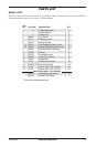
Special offers from our partners!

Find Replacement BBQ Parts for 20,308 Models. Repair your BBQ today.
www.desatech.com
105116-01D14
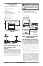
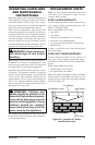
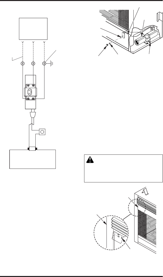
Figure 17 - Optional Blower Wiring
Diagram
INSTALLATION
Continued
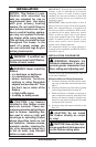
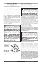
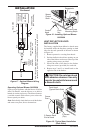
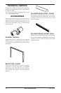
HEAT DEFLECTIVE HOOD
INSTALLATION
The factory supplied heat deective hoods must
be installed inside the replace opening on both
sides for the safe operation of the unit as shown
in Figure 19.
1. Remove protective covering from hoods.
2. Position deective hood into opening on one
side of the rebox and secure to the top of the
opening using screws provided.
3. Secure the ends of the hood to the rebox
using two screws (provided) for each side.
4. Repeat steps 2 and 3 to install hood on the
opposite side of the rebox.
CAUTION: Do not clean hood
with abrasive cleanser. Use only
regular household cleaners and
asmoothcloth.
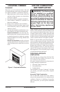
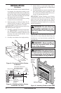
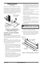
Blower
Receptacle
Hook and Loop
Mounting Strips
Control
Knob
Lock
Nut
Speed
Control
Shaft
Figure 18 - Installing Optional Blower
GA3500A
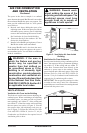
Operating Optional Blower GA3500A
Light your gas appliance with the blower off. After
about 10 minutes, turn the blower on to deliver
heated air out the top louvers. The blower features
a variable control which allows you to select the
blower speed you desire.
Note: Periodically check the louvers of the rebox
and remove any dust, dirt or obstructions.
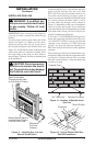
Figure 19 - Typical Hood Installation
(Both Sides)
2 Screws Each
End of Hood
Corner
Post
Front Hood
(Typical Each Side)
3 Screws
(Top)
INCOMING
120V AC
(FUSE BOX
OR
BREAKER)
BLK
BLK
GRN
GRN
WHT WHT
FIELD WIRE
GND
CONNECTORS
(NOT SUPPLIED)
VARIABLE
SPEED
CONTROL
BLOWER
RECEPTACLE
ELECTRICAL RATING:
120v, 60Hz, 0.9A
Note: If any of the original wire must be replaced, it must be
replaced with type TEW minimum 16GA copper wire rated at 105C