


Special offers from our partners!

Find Replacement BBQ Parts for 20,308 Models. Repair your BBQ today.
48049-136-05 Micrologic™ 2.0A, 3.0A, 5.0A, and 6.0A Electronic Trip Units
Rev. 01, 07/2012 Section 1—General Information
© 1999–2012 Schneider Electric All Rights Reserved
13-EN
ENGLISH
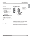
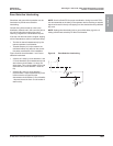
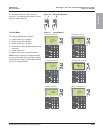
Indicator Lights
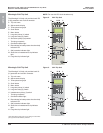
Ground-Fault Protection
Equipment ground-fault protection protects
conductors against overheating and faults from
ground-fault currents (d1200 A).
• Equipment ground-fault protection is
standard on 6.0A trip units.
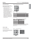
• Ground-fault pickup (Ig) (A) sets ground
current level where circuit breaker will trip
after the preset time delay.
• Ground-fault delay (tg) (B) sets the length of
time that the circuit breaker will carry a
ground-fault current above the ground-fault
pickup current level before tripping.
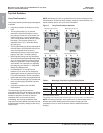
• Equipment ground-fault protection can be
zone-selective interlocked (ZSI) with
upstream or downstream circuit breakers.
• Setting the ground-fault delay (tg) to the 0
setting turns off zone-selective interlocking.
• Neutral protection and equipment ground-
fault protection are independent and can
operate concurrently.
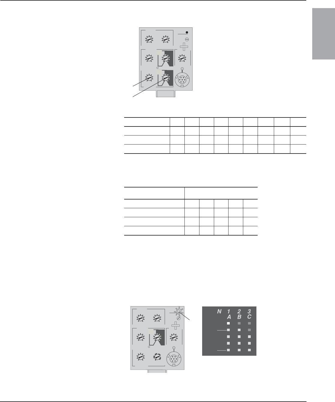
Figure 10: Ground-Fault Protection Switches
Table 4: Micrologic Trip Unit Ground-Fault Pickup Values
Ig (= In x....) ABCDEFG H J
In d 400 A 0.3 0.3 0.4 0.5 0.6 0.7 0.8 0.9 1
400 A < In d 1200 A 0.2 0.3 0.4 0.5 0.6 0.7 0.8 0.9 1
In > 1200 A 500 A 640 A 720 A 800 A 880 A 960 A 1040 A 1120 A 1200 A
In = sensor rating.
Ig = ground-fault pickup.
Table 5: Micrologic Trip Unit Ground-Fault Delay Values
Setting Ground-Fault Delay
I
2
t off (ms at In) (seconds) 0 0.1 0.2 0.3 0.4
I
2
t on (ms at In) (seconds) – 0.1 0.2 0.3 0.4
tsd (min. trip) (milliseconds) 20 80 140 230 350
tsd (max. trip) (milliseconds) 80 140 200 320 500
NOTE: Use I
2
t off with ZSI for proper coordination. Using I
2
t on with ZSI is
not recommended as the delay in the upstream device receiving a restraint
signal could result in the trip unit tripping in a time shorter than the
published trip curve.
.4
.5
.6
.7
.8
.9
.95
.98
1
delay
short time
I itsd
(s)
on
I
2
t
.
2
.
3
.
4
.
4
.
1
.
2
.
3
.
1
0
off
instantaneous
long time
alarm
Ir
x In
ground fault
B
C
D
E
F
G
H
J
Ig tg
(s)
on
I
2
t
.
2
.
3
.
4
.
4
.
1
.
2
.
3
.
1
0
off
A
.5
1
2
4
8
12
16
20
tr
(s)
@
6 Ir
24
setting
x Ir
2
2.5
3
4
5
6
8
10
Isd
1.
5
x In
3
4
5
8
10
12
15
off
2
test
06133351
A
B
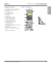
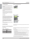
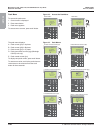
Micrologic 6.0A Trip Unit
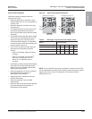
Overload Indicator Light
The overload indicator light (A) lights when the Ir
long-time pickup level has been exceeded (over
100% on the bar graph).
Figure 11: Overload Indicator Light
delay
short tim
e
I itsd
instantaneous
long time
alarm
test
800
earth leakage
1
2
3
5
7
10
20
30
ΔI
(ms)
60
.5
140
230
350
IΔn
(A)
setting
x Ir
2
2.5
3
4
5
6
8
10
Isd
1.
5
on
I
2
t
.
2
.
3
.
4
.
4
.
1
.
2
.
3
.
1
0
x In
2
2.5
3
4
5
6
8
10
1.
5
.5
1
2
4
8
12
16
20
tr
(s)
@
6 Ir
24
.4
.5
.6
.7
.8
.9
.95
.98
1
Ir
x In
40
%
%
100
06133352
A