


Special offers from our partners!

Find Replacement BBQ Parts for 20,308 Models. Repair your BBQ today.

9
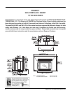
Regency U41-3 ULTIMATE Gas Fireplace Insert
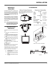
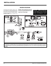
Draft Hood
Flue
guides
screw
holes
Spill Tube
Rear
Spill Tube
Front
INSTALLATION
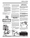
1) If the appliance is to be installed into an
existing chimney system, thoroughly clean
the masonry fi replace and have the chimney
swept.
GAS CONNECTION
For minimum and maximum supply pressure
see the System Data table on page 7.
Note: Prior to any pressure testing of the
gas supply piping system that ex-
ceeds test pressures of 1/2 psig, this
appliance and its individual shut-off
valve must be disconnected from
the piping system. If test pressures
equal to or less than 1/2 psig are used
then this appliance must be isolated
from the piping system by closing
its individual manual shut-off valve
during the testing.
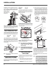
Valve Access: Loosen and remove the wing-
nuts on the both sides of the bottom louver and
then remove the louver.
GAS CONNECTION WARNING:
2) The gas connection is a 3/8" NPT male pipe
on the rear left side of the unit. The gas line
can be rigid pipe or to make installation
easier use a listed fl exible connector and
manual shut-off valve if allowed by local
building codes. A 1/2" gas supply pipe must
be brought near this inlet hole.
3) Locate the center point where the vent will
pass through the chimney above the appli-
ance. Move the appliance into the exact
location where it is to be installed. Ensure
that the Insert is level.
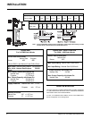
4) The gas control valve is provided with two
"IN" and "OUT" pressure taps, and are easily
accessible for a test gauge connection (see
diagram on page 9).
5) Once the gas has been connected ensure
that the pilot valve is in line with burner.
CAUTION: If the door is removed or opened
for servicing, it must be replaced and closed
prior to operating the appliance. The glass
must be fi xed in the door when operating.
COMBUSTION &
VENTILATION AIR
WARNING: This appliance needs fresh air
for safe operation and must be installed
with provisions for adequate combustion
and ventilation air available to the room in
which it is to be operating.
Follow CAN/CGA B149 (in Canada) or ANSI
Z223.1 (in the USA) requirements, and any
local codes or regulations of the enforcing
authority.
Air for combustion is drawn in through the front
of the unit, therefore, the front of the unit must
be kept clear of any obstructions.
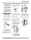
VENTING
THE APPLIANCE MUST NOT BE
CONNECTED TO A CHIMNEY FLUE
SERVING A SEPARATE SOLID FUEL
BURNING APPLIANCE.
This appliance is designed to attach to a 4"
diameter type B-Vent or double thickness alu-
minium fl ex liner running the full length of the
chimney. A minimum fl ue height of 12 feet is
recommended. B-Vent must be supported by a
vent support - supplied by vent manufacturer.
There must be at least 3 feet of chimney above
the roof level.
Stack the pipe onto your fi nish support to a
minimum height of 3 feet above the roof pen-
etration, or 2 feet above any point within 10 feet
measured horizontally. B-Vent chimneys require
a 1" clearance to combustibles.
Only persons licensed to work
with gas piping may make the
necessary gas connections to
this appliance.
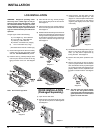
DRAFT HOOD
CONNECTION
1) Attach the vent to the fl ue collar on the
detachable draft hood. The fl ue collar of
the appliance will fi t inside a standard vent
and may be fastened directly to the vent by
sheet metal screw or a B-Vent, single wall
vent connector.
2) Before pushing the appliance into position
inside the fi replace, align the draft hood
with the guides on the insert top and push
forward. While pushing the unit back into
place keep pulling the draft hood forward until
the screw hole in the spill tube-rear aligns
with the screw hole in the spill tube-front. (If
screw holes do not line up then draft hood
is not positioned correctly.) Secure the two
spill tubes with a screw.
Note: Final gas connection should be after
unit is in place to avoid damage to line
when pushing the unit
into position.