


Special offers from our partners!

Find Replacement BBQ Parts for 20,308 Models. Repair your BBQ today.

10
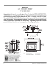
Regency U41-3 ULTIMATE Gas Fireplace Insert
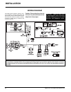
INSTALLATION
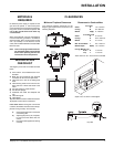
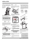
Before installing vent system ensure that the
damper plate is locked into the open position
and secure to prevent the damper plate from
falling down and crushing the liner.
GAS PRESSURE TEST
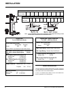
The unit is preset to give the correct gas input at
the specifi ed manifold pressures shown on the
label. The maximum gas manifold pressure is:
Natural Gas: 3.8" w.c.
Propane 11" w.c.
The manifold pressure is controlled by a regu-
lator built into the gas control, and should be
checked at the pressure test point. The pres-
sure check should be carried out with the unit
burning and the setting should be with in the
limits specifi ed.
Natural Gas: 3/16" open
Propane: 1/2" open
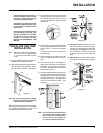
The aeration adjustment gears are located on
the right side of the burner box and can be ac-
cessed from the side or from the front when the
louvers are removed.
Note: Use the same manner to check the
inlet pressure.
AERATION SYSTEM
The burner aeration is factory set but may need
adjusting due to either the local gas supply, air
supply or altitude.
The Regency Insert incorporates its own inter-
nal draft hood, so no additional external draft
hood is required. Periodically check that the
vent is unrestricted and an adequate draft is
present when the
unit is in operation.
(See page 9 for
spillage test.)
To adjust the aeration: use the allen key to turn
the turning gear which will adjust the air shutter.
Open the air shutter for a blue fl ame or close it
for a yellower fl ame.
Clockwise to open,
counter-clockwise to close.
Caution: Carbon will be produced if the air
shutter is closed too much.
Note: Any damage due to carboning re-
sulting from improperly setting the
aeration controls is NOT covered
under warranty.
Note: Aeration Adjustment should only be
performed by an authorized Regency
Installer at the time of installation or
service.
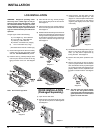
TEST FOR FLUE
SPILLAGE
A “spillage” test must be made before the in-
stalled unit is left with the customer. Follow the
procedure below:
1) Start all exhaust fans in the home and then
close all doors and windows in the room.
2) Light the unit and set controls to maximum.
Turn fan off.
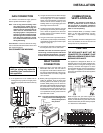
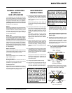
3) After fi ve minutes, test that there is a “pull”
on the fl ue by placing a smoke match,
cigarette or similar device which gives off
smoke, in front of the spill tube. To ensure
a valid test, place a scrap piece of sheet
metal (or other non-combustible material)
between the spill tube and the upper louver,
this will prevent the natural convection of
the unit from interfering with the test. See
diagrams below.
normal draft
downdraft or
blocked fl ue
Spill Tube
Non-combustible
Scrap
The smoke should be drawn into the spill tube,
if it does not, leave the unit for a further fi ve
minutes and retest as above. If the smoke is
still not drawn into the spill tube, turn the unit
off and check for the cause of the lack of draft.
If necessary, seek expert advice.
For wind turbulent sites, a wind cap may remedy
the problem.
Note: The thermally activated safety switch
will sense the change in temperature
and shut down the gas valve in the
event of a severe downdraft of air
or a blocked or disconnected vent.
The switch acts as a safety shut-off
to prevent a build up of carbon mon-
oxide. If the fl ue is blocked or has no
"draw", the switch will automatically