


Special offers from our partners!

Find Replacement BBQ Parts for 20,308 Models. Repair your BBQ today.

11
Regency U41-3 ULTIMATE Gas Fireplace Insert
INSTALLATION
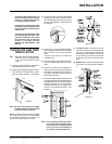
Tabs
Screws
Right
Side
To p
Hinged
Louvers
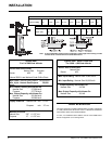
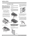
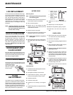
3) Using the trim clips provided, join the left side
gold trim (the one with the ON/OFF switch
and variable speed FAN switch) to the top
gold trim. See diagram 2. Repeat this step
for right side.
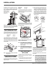
8) Fan Switch wires: Connect the plug end
from the fan switches to the matching plug
from the unit. See Diagram 5. Make sure
the plugs are pushed together as far as they
can go. Push the connection into the hole
in the side of the insert so it is locked into
place.
9) ON/OFF wires: Hook up the ON/OFF wires
to the switch on the left side trim. Diagram
5.
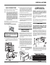
Trim Clips
tighten top
screw only
Rear View
Diagram 3
Diagram 4
Diagram 5
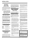
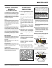
FACEPLATE AND TRIM
INSTALLATION
Hint: Before doing the faceplate installation,
leave the Insert out approximately
4" so wires may be hooked up more
easily.
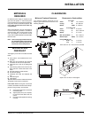
1) Lay the faceplate panels fl at, face down on
something soft so they don't scratch.
2) Take the top faceplate and align the holes in
it with the holes in the side panels. Attach,
using the screws provided. See diagram
1.
Diagram 1
Diagram 2
shut off the supply of gas within 5 - 10
minutes. Tampering with the switch
can result in carbon monoxide (CO)
poisoning and possible death.
If the heater turns off because of lack
of draft during the spillage test, check
for the cause and if necessary, seek
expert advice.
The thermally actuated safety switch
will automatically reset after it has
reduced in temperature. The switch
will continue to cycle until the draft
problem is corrected. DO NOT
BYPASS OR DISCONNECT THIS
SWITCH.
Note: The holes in the top panel are slightly
larger than the holes in the side panel
to facilitate easier installation.
Hint: Don't tighten the screws down completely
at this point, fi rst do a trial fi t to the unit. Make
any necessary adjustments and when it fi ts
properly then tighten down the screws.
4) Place the trim on the assembled faceplate
panels, aligning the wires from the switches
with the notch in the left side faceplate
panel.
The power cord should be run behind the
faceplate panel.
5) Push the Regency logo plate into the two
holes in the bottom left corner of the face-
plate.
6) Secure the brass trim to the faceplate by
drilling a 1/8" hole through into the faceplate
side fl ange, using the hole in the brass trim
as a guide. Now fasten with the two brass
plated screws provided.
7) Lift the assembled faceplate up and over the
top of the insert and then lower it down so the
faceplate tabs are in line with the faceplate
brackets. See diagram 3. Once everything
is properly lined up you can tighten the 4
screws on the faceplate brackets. See
diagram 4.
Note: If you are making custom face-plates,
you must use the faceplate louvers.
Failure to do so will void the certifi ca-
tion on your unit. The faceplate lou-
vers can be purchased separately.