


Special offers from our partners!

Find Replacement BBQ Parts for 20,308 Models. Repair your BBQ today.
Be sure that the fuel source designated on your
grill head is the same as that of the support
system.
DO NOT USE A GRILL HEAD EQUIPPED
FOR NATURAL GAS WITH LP GAS OR
THE OPPOSITE.
Maximum inlet pressure from System LP cannot
exceed 11" W.C. The proper orifices and valving for
each gas is contained in the grill head. Maximum
pressure for Natural Gas is 7" W.C.
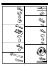
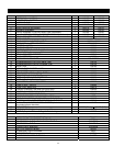
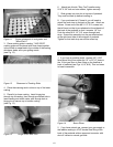
3. VERIFY ALL PARTS. IF YOU ARE MISSING ANY
PARTS, PLEASE CONTACT YOUR PGS DEALER.
4. REMOVE PROTECTIVE FILM FROM ALL
STAINLESS STEEL COMPONENTS (Be careful not
to scratch stainless steel parts).
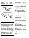
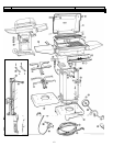
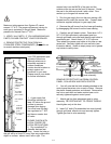
PERMANENT POST (IN GROUND) MOUNTING
Your PGS permanent post
is made of aluminum.
Although aluminum is
extremely resistant to
outdoor conditions,
caution should be taken to
protect against soil
ns in your area.
Please consult your dealer
for further information.
conditio
GRILL
B
POS
INTO
1. A g
surface
damage
You mu
line r
and hav
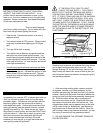
CONTROL
PANEL
STIFFENING
BRACKETS
IN-GROUND
8”POST
STAINLESS
STEELTUBING
ACCESS
DOOR
3/8” FLARE
COUPLING
(Not Included)
GAS SUPPLY
LINE
ACCESS
HOLE ON
BACK OF
POST
8” DIA. HOLE
24” DEEP
CEMENT
PLEASE NOTE: THE
HEAD IS NOT TO
E FASTENED TO THE
48" POST UNTIL THE
T IS CEMENTED
THE GROUND.
as supply line
should be trenched at
least 18" below the ground
to prevent
from digging.
st have a supply
egulated to 7" W.C.
e a master shut
off valve.
PLEASE CHECK WITH
LOCAL CODES FOR
LOCAL REGULATIONS.
2. Dig a posthole 8" in
diameter and two feet
deep. Locate the hole so
the grill will be at least 30" away from any combustible
object or surface: above, back, left or right. The
access hole is on the BACK of the post and the
notches at the top are on the front of the post. Center
the post in the hole and plumb it with a level. Pour
cement up to the gas line access hole.
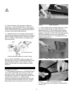
3. Run the gas supply line into the post making a 90-
degree bend to reach the access door. Connect steel
connector supplied with post to gas supply line.
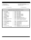
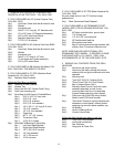
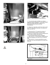
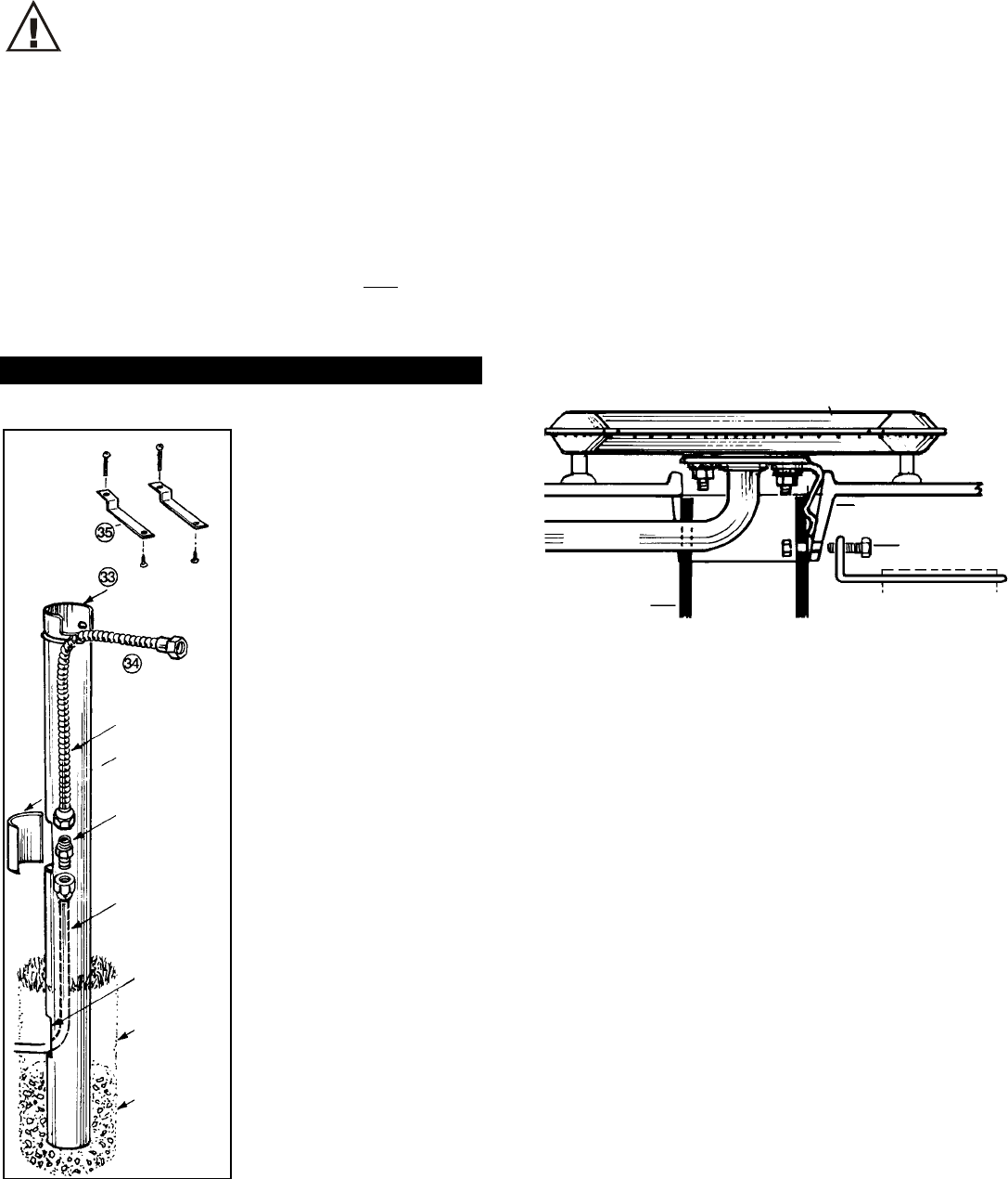
4. Remove the grill burner from the lower grill casting
by disengaging the burner from the lower casting.
5. Carefully set grill head in place. Pass three 1/4" X
20" X 3/4" bolts provided in permanent post box
through grill head cast collar and then through holes in
permanent post. Attach three 1/4" X 20" kep nuts.
Then attach the grease cup holder at this time on rear
center bolt. Securely tighten all nuts and bolts (see
illustration below). Insert an empty soup can in grease
cup holder to catch juices.
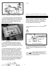
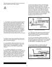
K-30 BURNER
POST FLANGE
VENTURI
BOLTS
ATT
ACH POST
GREASE CUP
POST HOLDER
Grill head to permanent post assembly
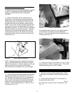
REMOVE PROTECTIVE FILM FROM CONTROL
PANEL, COLLAR BOX AND ROCK GRATES
6. You will note that the bolts already attached to the
control panel have two nuts on each of them. Remove
the plastic thread protectors and discard. Remove the
top nut on each bolt and make certain lower nut is
securely tightened against control panel.
7. Attach gas line from permanent post to valve
assembly. BE CERTAIN NOT TO CROSS THREAD.
Hand-tighten only at this time.
8. Insert 3/4" bolts (Pre-assembled on control panel)
through grill head, attach nuts and securely tighten.
Tighten gas line to valve assembly.
14