


Special offers from our partners!

Find Replacement BBQ Parts for 20,308 Models. Repair your BBQ today.

6
W415-0171 / E / 01.10.05
FIGURE 7
FIGURE 8
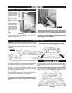
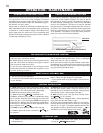
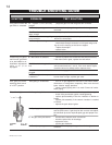
This is a thermally activated switch, attached to the back of
the unit and extending up into the dilution draft hood, which
senses the change in temperature and shuts down the
gas valve in the event of a severe downdraft of air or a
blocked or disconnected vent. It acts as a safety shutoff to
prevent a build up of carbon monoxide or an explosion of
unburnt gases during start up. If the flue is blocked or has
no "draw", the spill switch will automatically shut off the
supply of gas within about 5-10 minutes.
TAMPERING WITH THE SWITCH CAN RESULT IN
CARBON MONOXIDE (CO) POISONING AND POS-
SIBLE DEATH.
A check for correct venting action must be made be-
fore the installed insert is left with the customer.
Test after installing the unit into either the GI-700 ZERO
CLEARANCE KIT or a vented noncombustible fireplace in
the following manner:
1. Close all doors and windows in the room / start exhaust
fans in the home / turn fireplace blower off.
2. Set controls to "high" and light the unit.
3. Wait 5 minutes. Light a match and hold it to the spill tube
opening.
4. Venting action is satisfactory if smoke is drawn into the
spill tube. Venting action is unsatisfactory if the flame and
smoke are not drawn into the tube.
5. If venting action is unsatisfactory, turn the unit off, wait
10 minutes and try again. If the smoke or flame is still not
drawn into the spill tube, turn the unit off and check for
adequate fresh air supply, vent blockage or restriction. If
necessary, consult with a qualified inspector.
SPILL SWITCH
VENTING ACTION CHECK
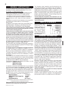
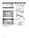
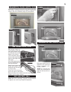
Levelling the insert will eliminate rocking or excessive noise
when the fan is in operation. Replace the securing screw
to the front of the dilution plate.
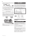
Install rigid black pipe, a flex connector, if local codes per-
mit, or 1/2" type L, copper tubing with a 3/8" to 1/2" adapter
and a shut off valve to the fireplace. Seal and tighten se-
curely. The adapter will be required between the gas valve
and the copper tubing or flex connector.
Do not damage or kink flex connector!
Check for gas leaks by brushing on a soap and water solu-
tion.
Do not use open flame!
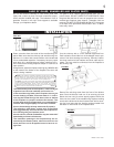
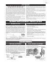
An on/off switch has been included and can be located at
the lower right, behind the louvre access door or at the right
side trim.
For ease of accessibility, this switch may be replaced with
a wall switch or substituted with a millivolt thermostat that
may be installed in a convenient location on any wall. Route
2-strand (solid core) millivolt wire through the electrical
hole located at the bottom right side of the unit. The recom-
mended maximum lead length depends on wire size:
WIRE SIZE MAX. LENGTH
14gauge 100 feet
16gauge 60 feet
18gauge 40 feet
Attach the two leads to terminals 1 and 3 located on the
gas valve.
Do not connect either the wall switch or the gas valve to
electricity (110 volts or 24 volts).
FIGURE 5
FIGURE 6
1
2
3