


Special offers from our partners!

Find Replacement BBQ Parts for 20,308 Models. Repair your BBQ today.

4
W415-0171 / E / 01.10.05
The fireplace, when installed, must be electrically con-
nected and grounded in accordance with local codes. In
the absence of local codes, use the current CSA C22.1
CANADIAN ELECTRICAL CODE in Canada or the
ANSI/NFPA 70 NATIONAL ELECTRICAL CODE in the United
States. The blower power cord must be connected into a
properly grounded receptacle. The grounding prong must
not be removed from the cord plug.
Provide adequate ventilation and combustion air. Pro-
vide adequate accessibility clearance for servicing and
operating the fireplace. Never obstruct the front open-
ing of the fireplace.
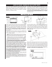
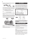
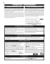
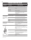
Mantle clearance, while
conforming to the
stated clearance to
combustible materials,
can vary according to
the mantle depth.
These clearances do
not apply to a GI-700 kit
type installation.
FOR YOUR SATISFACTION, THIS FIREPLACE HAS BEEN
TEST-FIRED TO ASSURE ITS OPERATION AND QUAL-
ITY! Maximum input is 30,000 BTU/hr for natural gas and
24,000 BTU/hr for propane. For elevations between 2,000
and 4,500 feet above sea level, this fireplace must be de-
rated by 10% using the certified high altitude kit. When the
fireplace is installed at elevations above 4,500 ft., and in
the absence of specific recommendations from the local
authority having jurisdiction, the certified high altitude input
rating shall be reduced at the rate of 4% for each additional
1,000 ft. Maximum output for natural gas is 22,800 BTU/hr
at an efficiency of 76% with the fan on, 72% with the fan off;
and 18,240 BTU/hr for propane at an efficiency of 76% with
the fan on, 71% with the fan off. Minimum A.F.U.E.(Annual
Fuel Utilization Efficiency) rating is 64% for both natural
and propane gas. This fireplace is approved for bathroom,
bedroom and bed-sitting room installations and is suit-
able for mobile home installation.
Minimum inlet gas supply pressure is 4.5 inches water
column for natural gas and 11 inches water column for
propane. Maximum inlet gas pressure is 7 inches water
column for natural gas and 13 inches water column for
propane. Manifold pressure under flow conditions is 3.5
inches water column for natural gas and 10 inches water
column for propane.
No external electricity (110 volts or 24 volts) is required
for the gas system operation.
Change in flame appearance from "HI" to "LO" is more
evident in natural gas than in propane. The self generating
pilot provides current for a remote burner On-Off switch.
Installation practices vary from region to region and it is
important to know the specifics that apply to your area,
for example: in Massachusetts State:
• The fireplace damper must be removed or welded in the open
position prior to installation of a fireplace insert or gas log.
• The appliance off valve must be a “T” handle gas cock.
• The flexible connector must not be longer than 36 inches.
• The appliance is not approved for installation in a bedroom or
bathroom unless the unit is a direct vent sealed combustion
product.
• WARNING: This product must be installed by a licensed plumber
or gas fitter when installed within the commonwealth of
Massachusetts.
In absence of local codes, install to the current CAN1-B149
Installation Code in Canada or to the National Fuel Gas
Code, ANSI Z223.1, and NFPA 54 in the United States.
Purge all gas lines with the glass door of the fireplace
removed. Assure that a continuous gas flow is at the
burner before installing the door.
Under extreme vent configurations, allow several minutes
(5-15) for the flame to stabilize after ignition. Altitudes
greater than 4,000 ft. require a minimum vent run of 12 ft.
The heater and its individual shutoff valve must be discon-
nected from the gas supply piping system during any pressure
testing of that system at test pressures in excess of ½ psig (3.5
kPa). The fireplace must be isolated from the gas supply pip-
ing system by closing its individual manual shutoff valve during
any pressure testing of the gas supply piping system at test
pressures equal to or less than ½ psig (3.5 kPa).
A 1/8 inch NPT plug, accessible for test gauge connection,
must be installed immediately upstream of the gas supply
connection to the fireplace.
This fireplace must be connected to any accepted lined chim-
ney system listed to ULC-S635M (in Canada) or UL-1777
(in USA). The venting connection must be in compliance
with the chimney manufacturers installation instructions.
The draft hood must be installed so that it is in the same
atmospheric pressure zone as the combustion air inlet to
the fireplace.
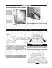
This heater can be installed two different ways. If installed
as is, it must be recessed into a vented noncombustible
woodburning fireplace (prefabricated or masonry) only. This
is referred to as an INSERT type of installation.
The minimum fireplace size in which the heater is to be
installed is: HEIGHT 21 inches
WIDTH 26½ inches
DEPTH 17½ inches
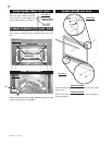
If installed in conjunction with kit #GI-700, it may be framed
into an enclosure made of combustible materials. This is
referred to as a ZERO CLEARANCE type of installation.
This heater may only be installed in the GI-700 when using
the glass front kit, GI-FF, as well as one louvre kit, GI-LPB,
GI-LAB, GI-LG or GI-LK. The minimum clearance to com-
bustible construction in this form of installation is:
MANTLE HEIGHT* 7 inches
**
SIDES, BACK, BOTTOM & TOP 0 inches
B-VENT 1 inch
RECESSED DEPTH 18½ inches
* MEASUREMENTS TAKEN FROM KIT STANDOFFS. SEE KIT INSTRUCTIONS
**MAXIMUM HORIZONTAL EXTENSION IS 6 INCHES.
Objects placed in front of the fireplace must be kept a
minimum of 48" away from the front face.
GENERAL INSTRUCTIONS
MANTLE CLEARANCE
GENERAL INFORMATION
FIGURE 1