


Special offers from our partners!

Find Replacement BBQ Parts for 20,308 Models. Repair your BBQ today.

11
W415-0171 / E / 01.10.05
3. Check to see that all burner ports are burning. Clean out
any of the ports which may not be burning or are not burn-
ing properly. (right brick panel must be removed in order to
facilitate burner removal)
4. Check to see that the pilot flame is large enough to
engulf the thermopile on one leg and reaches toward the
burner on the other leg.
5. Replace the cleaned logs.
6. Check to see that the main burner ignites completely on
all openings when the gas knob for the burner is turned
on. A 5 to 10 second total light-up period is satisfactory. If
ignition takes longer, consult your Napoleon dealer / dis-
tributor.
7. Check that the gasketing on the door is not broken or
missing. Replace if necessary.
TURN OFF THE GAS AND ELECTRICAL POWER
BEFORE SERVICING THE FIREPLACE.
CAUTION: Label all wires prior to disconnection when serv-
icing controls. Wiring errors can cause improper and dan-
gerous operation. Verify proper operation after servicing.
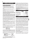
This insert and its venting system should be inspected
before use and at least annually by a qualified service per-
son. The fireplace area must be kept clear and free of
combustible materials, gasoline or other flammable va-
pours and liquids. The flow of combustion and ventilation
air must not be obstructed.
1. In order to properly clean the burner and pilot assembly,
remove the logs to expose both assemblies.
2. Keep the control compartment, logs, burner, air shutter
opening and the area surrounding the logs clean by vacu-
uming or brushing, at least once a year.
FIGURE 21
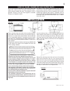
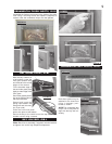
The Napoleon gas fireplace insert comes standard with a
blower, a heat sensor, variable on/off speed control and a
power cord. Because the blower is thermally activated,
when turned on, it will automatically start approximately 15
minutes after lighting the fireplace and will run for approxi-
mately 30 minutes after the fireplace has been turned off.
Use of the fan increases the output of heat. Air, drawn in
through the lower louvre access door, is driven up the back
of the firebox, and exhausted as hot air between the upper
louvres.
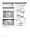
• Turn off the gas and electric power to the unit.
• Remove the glass door.
• Remove the lower glass bracket.
• Remove the logs.
• Remove the burner assembly. (right brick panel must
be removed in order to facilitate removal)
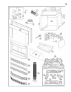
• Remove the four screws holding the access door in
place on the control assembly (located to the back of
the burner assembly.) For location, see picture in re-
placement parts.
• Disconnect the electrical connectors at the blower.
• Remove the blower.
FIGURE 23
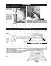
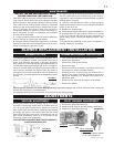
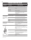
1. Remove the pilot adjustment cap.
2. Adjust the pilot screw to provide properly sized flame.
3. Replace the pilot adjustment cap.
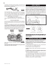
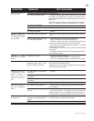
Natural gas models have air shutters set at 1/16 (.063")
inch open. Propane gas models have air shutters set at [5/
16] (.313) inch open. Closing the air shutter will cause a
more yellow flame, but can lead to carboning. Opening the
air shutter will cause a more blue flame, but can cause
flame lifting from the burner ports. The flame may not ap-
pear yellow immediately; allow 15 to 30 minutes for the
final flame colour to be established.
AIR SHUTTER ADJUSTMENT MUST ONLY BE DONE BY A
QUALIFIED GAS INSTALLER!
PILOT ASSEMBLY
FIGURE 25
PILOT ADJUSTMENT
CAP
FLAME MUST ENVELOP UPPER
3
/
16
" TO ½" OF THERMOPILE
THERMOPILE
Drywall dust will penetrate into blower bearings causing irrepairable damage and must be prevented from coming into
contact with the blower or its compartment.
Any damage resulting from this condition is not covered by the warranty policy.
MAINTENANCE
BLOWER REPLACEMENT INSTALLATION
BLOWER SYSTEM
BLOWER REPLACEMENT INSTRUCTIONS
ADJUSTMENTS
PILOT BURNER ADJUSTMENTVENTURI ADJUSTMENT
FIGURE 24