


Special offers from our partners!

Find Replacement BBQ Parts for 20,308 Models. Repair your BBQ today.

2
Important Safety Instructions and Precautions
WARNING:DO NOT CONNECT DIRECTLY TO THE PUBLIC SWITCHED
TELEPHONE NETWORK (PSTN). ANY CONNECTION OF THIS MODULE
TO AN OFF PREMISE APPLICATION, AN OUT OF PLANT APPLICATION,
ANY OTHER EXPOSED PLANT APPLICATION, OR TO ANY EQUIPMENT
OTHER THAN THE INTENDED APPLICATION MAY RESULT IN A SAFETY
HAZARD, AND/OR DEFECTIVE OPERATION, AND/OR EQUIPMENT
DAMAGE. “EXPOSED PLANT” MEANS WHERE ANY PORTION OF THE
CIRCUIT IS SUBJECT TO ACCIDENTAL CONTACT WITH ELECTRIC
LIGHTING OR POWER CONDUCTORS OPERATING AT A VOLTAGE
EXCEEDING 300 V BETWEEN CONDUCTORS OR IS SUBJECT TO
LIGHTNING STRIKES.
Maintenance and Repair
The IP PKM IM/PKM 12/PKM 48 are field replaceable units. There are no user
serviceable parts inside the modules. For repairs, return the module to an
authorized Mitel dealer.
These notices may appear on the product or in the technical documentation.
This symbol may appear on the product.
Description
The IP Programmable Key Modules (PKM) are peripheral devices providing
connectivity (the Interface Module) or additional personal keys (the IP PKM12
and IP PKM48) for IP and Digital Phones. Each personal key may be
programmed as a feature key, Speed Call keys, Direct Station Select (DSS)
keys, or line appearance keys, and each has a line status indicator.
The IP Programmable Key Module (PKM) Interface Module (IM) provides
connectivity between the 5220/5224/5235/5324/5330/5340 IP Phones or 8528/
8568 Digital Phones and the IP PKM 12 /IP PKM 48. The IP PKM IM allows you
to connect your 5220/5224/5235/5324/5330/5340 IP Phone or 8528/8568
Digital Phone to a single IP PKM 12. A maximum of two IP PKM 48s may be
attached to a 5220/5224/5235/5324/5330/5340 IP Phone supported by a Mitel
Communications Director (MCD), 3300 IP Communications Platform (ICP) or
SX-200 ICP, or an 8528/8568 Digital Phone and 5224/5324 IP Phone supported
by a 5000 Communications Platform, for a maximum of 96 additional keys.
NOTE:
The IP PKM IM, IP PKM12, and IP PKM48 cannot be installed on a
phone that has a Line Interface Module, 5310 Conference Unit, or
Cordless Module installed.
Powering Requirements
The IP PKM Interface Module (IM) supplies the power to the IP PKM12 and IP
PKM48. There are different powering requirements depending on which phone
the IP PKM and IP PKM IM is attached to, as follows:
• 5220/8528/8568: The DC adapter (24 v, PN50005300) that powers the
host 5220 IP Phone and 8528/8568 Digital Phone powers the IP PKM IM
and the IP PKM 12/48.
The DC adapter is always required to power the IP PKM IM when used on
a 5220 IP Phone or 8528/8568 Digital Phone.
• 5224/5235/5324/5330/5340: The IP PKM IM supports Power over Ethernet
(PoE) from the Phone to power the IP PKM 12/48.
The DC adapter (48 v) is not required when using a PKM 12/48 or two IP
PKM48s on a 5224/5235/5324/5330/5340 IP Phone that is powered by
PoE.
System Software Requirements
The IP PKM IM, IP PKM12, and IP PKM48 are supported by the following
system software:
• MCD Release 4.1 SP3 and later software
• 5000 Communications Platform Release 3.2 and later software
• SX-200® ICP Release 4.0 UR5 and later software.
NOTE:The IP PKM 12 and IP PKM 48 are the only PKMs qualified by Mitel
for connection to the 5220/5224/5235/5324/5330/5340 IP Phones and
8528/8568 Digital Phones.
CAUTION:Only personnel qualified by Mitel should install the IP PKM IM.
Supporting Documentation
For more information refer to the appropriate system-specific technical
documentation available at Mitel Online. To access the 5220/5224/5235/5324/
5330/5340 IP Phone and 8528/8568 Digital Phone documentation:
1. In your browser, go to www.edocs.mitel.com.
2. Click End User Documents in the menu bar or under Other Resources
in the left side navigation pane.
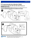
IP PKM IM Installation Instructions
To install an IP PKM IM (see Figure on previous page)
CAUTION:Handle the IP PKM IM by the cover. Do not touch components or circuitry.
Unplug the phone from the system.
With a Phillips screwdriver, remove the screw from the module cover from
the under side of the phone. Store the cover and screw.
NOTE:If you are using the IP PKM IM with a 5220/5224/5324/5330/5340 IP
Phone, punch out the PC port tab of the IP PKM IM before installation.
This does not apply to the 5235 IP Phone.
For a 5330/5340 IP Phone only:
• Plug the jumper cable (included with the IP PKM IM) into the 4-pin
cable connector on the main board of the 5330/5340 IP Phone.
• Align the IP PKM IM against the phone and attach the other end of the
jumper cable to the IP PKM IM connector.
Place the IP PKM IM and apply equal pressure to all sides of the cover until
the IP PKM IM clicks into place.
Fasten the IP PKM IM cover with the supplied screw.
Reconnect the phone to the system and plug the power adapter or PoE
LAN cable into the phone.
CAUTION:Use only with Mitel Networks power supply.
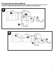
To remove an IP PKM IM (see Figure on previous
page)
Unplug the phone from the system, power adapter, and all cables from the
IP PKM IM jacks. Unplug the power adapter from its power source.
With a Phillips screwdriver, remove the screw from the IP PKM IM from the
under side of the phone. Store the screw. Grasp the IP PKM IM and gently
pull the IP PKM IM from the phone.
Replace the phone's original cover and fasten it with the screw removed in
Step 2 of installing an IP PKM IM.
Reconnect the system and interface cables to the phone.
DANGER
Danger indicates an imminently hazardous situation which, if not
avoided, will result in death or serious injury.
WARNING
Warning indicates a potentially hazardous situation which, if not
avoided, could result in death or serious injury.
CAUTION
Caution indicates a potentially hazardous situation which, if not
avoided, may result in minor or moderate injury and/or damage to the
equipment or property.
The exclamation point within an equilateral triangle indicates that
important operating and maintenance (servicing) instructions are included
in the literature accompanying the product.
!
A
B