


Special offers from our partners!

Find Replacement BBQ Parts for 20,308 Models. Repair your BBQ today.

NOTE: DIAGRAMS & ILLUSTRATIONS NOT TO SCALE.
8
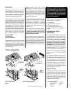
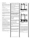
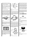
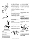
Step 4. Fireplace should be secured to side
framing members using the full length nailing
tabs at the top and bottom of the fireplace front
face. Use 8d nails or equivalent (
Figure 17
).
Figure 17
Note: The nailing tabs and the area directly
behind the nailing tabs are exempt from the
clearances described on page 5. Maintain at
least 1/2" clearance from the firebox wrapper to
the framing at the closest point of contact,
directly adjacent to the flange.
For Canadian Installations
A cold Climate Kit FTF8-CCK2-LD must be
installed. CCK2 kits are available from
FireCraft through your local dealer. Installer
must supply suitable length of 6" Diameter,
class "0" metallic air duct.
Proceed with Steps 5 through 8
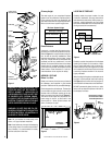
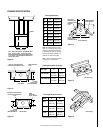
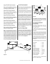
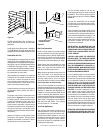
Step 5. Install the Cold Climate Kit to the
fireplace following the instructions provided
with the kit, (
Figure 18
).
Figure 20
8d Nail Or
Equivalent
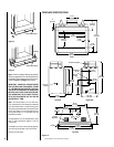
Framing must maintain adequate minimum air
space clearance at all times.
CAUTION: ALLOW MINIMUM 2" CHIMNEY
AIR SPACE TO COMBUSTIBLE FRAMING MEM-
BERS THROUGHOUT VERTICAL OR OFFSET
CHIMNEY INSTALLATION.
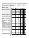
A minimum 2" air space must be reserved for
all combustible materials extending for any
continuous length surrounding the chimney.
Reference
Figures 15 and 16
and charts Fram-
ing Dimensions for Ceiling and Roof, which
specify minimum ceiling and roof dimensions.
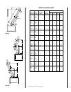
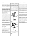
In new construction, to determine chimney cen-
ter line, use plumb line from roof or ceiling above
fireplace to center of flue collar on fireplace.
For remodeling, plumb to center of flue collar
from ceiling above, drive nail through ceiling
from below to mark position, then mark and
cut to passage from above ceiling (around
nail) (
Figure 20
). Then plumb from ceiling or
roof level directly above hole which has just
been completed.
Figure 18
Install Screws
Chimney
Duct
Duct
Collar
Front Cover
Plates
Side Cover
Plate
Step 6. Connect the 6" (102 mm) Class 0 air
duct provided by installer, to the duct collar on
the fireplace and secure with two (2) screws
from the kit’s hardware package.
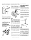
Step 7. Route the Class 0 air duct out the back
or side wall, up through the ceiling or floor
joists to an outside wall. The air inlet hood
should be located above snow level or above
any anticipated snow level, (
Figure 19
).
Figure 19
Note: If the fireplace is installed against an
inside wall, the class 0 air duct may be ex-
tended into a ventilated attic space at least 18"
(475mm) above the attic floor. Secure the air
inlet hood to a vertical post with the inlet
positioned downward. Ensure that nothing
blocks the hood opening. This hood must
never terminate higher than three (3) feet
below the termination.
Step 8. Cut or frame a hole through the outside
wall for the installation of the air inlet hood. A
6-1/2" diameter hole is required. Feed the loose
end of the flexible duct through the hole and
attach to the collar on the air inlet hood using
two (2) screws from the kit's hardware pack-
age. Insert the hood into the opening. Secure
the inlet hood in place with nails driven through
the holes in the flange. Seal with noncombus-
tible waterproof silicon type caulking.
INSTALLING THE CHIMNEY SYSTEM
Step 1. Before continuing, check the operation
of the damper, as described on page 4, (
refer to
Figure 3
).
Step 2. Using standard construction framing
techniques, construct opening for chimney route
up through the ceiling(s) and roof or through an
outside chase.
Install As Shown With Opening
In Downward Position, Do Not
Block Entrance
5 Foot Min. Height
From Outside
Ground Level
Step 3. Position appropriate firestop spacer at
ceiling and fasten temporarily with two (2) 8d
nails or equivalent. Use flat firestop spacer,
Model F8FS-2, if chimney penetrates ceiling
vertically. If chimney penetrates ceiling at 30°
angle (offset chimney), use 30° firestop spacer,
Model F8FS30-2. Use one nail on opposite
sides to hold firestop spacer in position. Nail
permanently, using at least two (2) more 8d
nails, after chimney sections have been as-
sembled through the firestop spacer and after
any necessary adjustments have been made.
Firestop spacer must be secured by at least four
(4) 8d nails when completely installed.