


Special offers from our partners!

Find Replacement BBQ Parts for 20,308 Models. Repair your BBQ today.

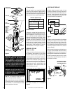
NOTE: DIAGRAMS & ILLUSTRATIONS NOT TO SCALE.
7
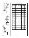
Figure 15
Figure 16
Figure 14
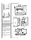
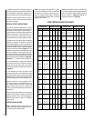
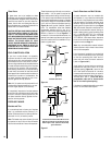
Framing Dimensions
A 43" 1092 mm
B 44-1/2" 1130 mm
C 29-1/2" 749 mm
D 15-3/4" 400 mm
E 73" 1854 mm
F 36-1/2" 927 mm
G 21-3/4" 552 mm
H 20-3/4" 527 mm
J 51-5/8" 1311 mm
Framing Dimensions for Roof
Pitch C D*
0/12 16-1/2" 16-1/2"
(419 mm) (419 mm)
6/12 16-1/2" 19"
(419 mm) (483 mm)
12/12 16-1/2" 23-1/2"
(419 mm) (597 mm)
Framing Dimensions for Ceiling
Flue Type A B
FTF8 Vertical 16-1/2" 16-1/2"
(419 mm) (419 mm)
FTF8 Offset 30° 16-1/2" 25"
(419 mm) (635 mm)
* Perpendicular to roof ridge
A
B
Ceiling Framing
C
D
Roof Framing
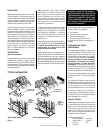
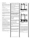
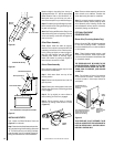
FRAMING SPECIFICATIONS
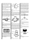
Figure 11
Figure 12
Figure 13
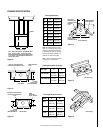
A
G
Inside Chase
Back Wall of Chase/Enclosure
Including Finising Materials if any
Rough
Framing Face
(Unfinished Shown)
FOAK Combustion
Air Kit
A
Outside Chase
G
H
Back Wall of Chase/Enclosure
Including Finising Materials
if any
Rough
Framing Face
(Unfinished Shown)
FOAK
Combustion
Air Kit - Optional
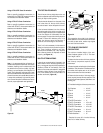
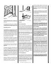
Corner Installation
J
D
A
E
F
Back Wall of
Chase/Enclosure
Including Finising
Materials
if any
Rough
Framing Face
(Unfinished Shown)
FOAK Combustion
Air Kit - Optional
C
Header
Fireplace Framing
B
A
Note: When Framing With 6” Studs Header Must
Be 17” (432mm) Higher. Use Security’s OR15
Offset/Return Elbow To Recess The Chimney Back
2 1/2” (64mm). Maintain Required Clearance To
Chimney At All Times.
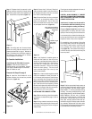
Note: All framing dimensions calcu-
lated for 5/8" nailing flange depth
and 1/2" dry wall at the fireplace face.
If sheathing the chase or finishing
with other thickness materials, cal-
culations will need to be made.
Note: C and G dimensions include
1" clearance to combustibles.