


Special offers from our partners!

Find Replacement BBQ Parts for 20,308 Models. Repair your BBQ today.
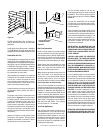
NOTE: DIAGRAMS & ILLUSTRATIONS NOT TO SCALE.
6
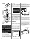
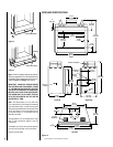
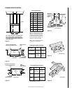
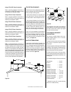
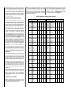
FIREPLACE SPECIFICATIONS
Figure 10
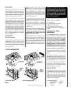
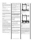
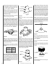
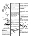
Blocking
Metal Safety Strips
Figure 8
Figure 9
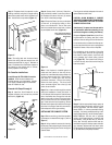
Step 3. Refer to fireplace drawings and specifi-
cations on pages 6 and 7 for framing dimensions
and details. Frame appliance enclosure as illus-
trated in
Figures 11 through 14
on page 8.
IMPORTANT: UNDER NO CIRCUMSTANCES
CAN THE FIREPLACE TOP SPACERS (
FIGURE
10
) BE REMOVED OR MODIFIED, NOR MAY
YOU NOTCH THE HEADER TO FIT AROUND OR
BE INSTALLED LOWER THAN THE SPACERS.
THE HEADER MAY BE IN DIRECT CONTACT
WITH THE TOP SPACERS BUT MAY NOT BE
SUPPORTED BY THEM.
Note: The framed depth, 21-3/4" (552 mm)
from a framed wall, must always be measured
from a finished surface. If a wall covering such
as drywall is to be attached to the rear wall, then
the 21-3/4" (552 mm) must be measured from
the drywall surface. It is important that this
dimension be exact.
If the appliance is to be elevated above floor
level, a solid continuous platform must be
constructed.
The header may rest on the top metal spacers,
but must not be notched to fit around them.
Consult all local codes.
41-3/4"
(1060 mm)
28-1/8"
(714 mm)
8-1/16"
(205 mm)
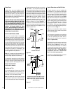
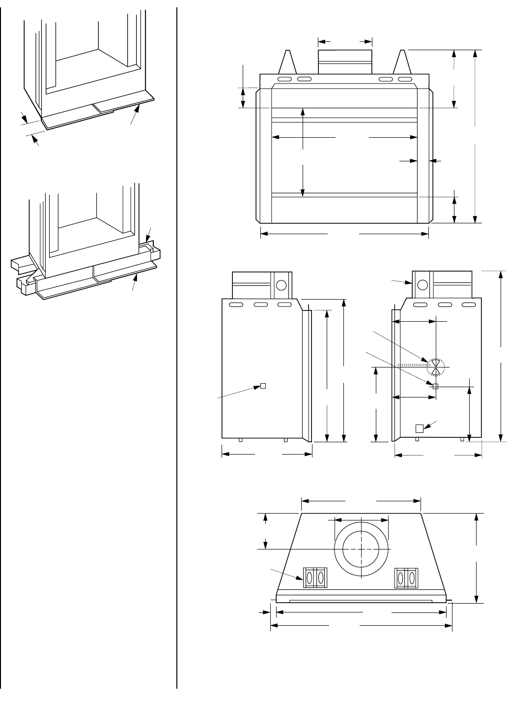
Top View
Right Side
Gas Line
Access
Junction
Box
Combustion
Air Inlet
9-7/8"
(251 mm)
44-1/4"
(1124 mm)
20-11/16"
(525 mm)
39-3/16"
(995 mm)
21-5/16"
(541 mm)
Left Side
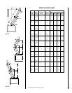
41-3/4"
(1060 mm)
Front
44-1/4"
(1124 mm)
7-1/8"
(181 mm)
36"
(914 mm)
2-7/8"
(73 mm)
12-1/2"
(318 mm)
20-3/16"
(513 mm)
16-15/16"
(428 mm)
9"
(229 mm)
Fireplace Top Spacer
Fireplace
Top Spacer
Gas Line
Access
17-7/16"
(443 mm)
10-1/8"
(257 mm)
43-3/4"
(1111 mm)
1"
(25 mm)
36-5/16"
(922 mm)
21-5/16"
(541 mm)
12-1/2"
(318 mm)
11-7/16"
(290 mm)
Metal Safety Strips
1-1/2"