


Special offers from our partners!

Find Replacement BBQ Parts for 20,308 Models. Repair your BBQ today.
NOTE: DIAGRAMS & ILLUSTRATIONS NOT TO SCALE.
14
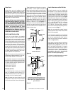
Figure 43
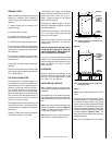
THIS FIREPLACE IS NOT INTENDED TO BE
USED AS A SUBSTITUTE FOR A FURNACE TO
HEAT AN ENTIRE HOME. USE FOR SUPPLE-
MENTARY HEATING ONLY.
HOUSE
WIRING
COVER PLATE
Replace Cover Plate
After Electrical
Hook-Up
POWER TO THE FIREPLACE
The Optional Blower Kit
Operates on 115 volt 60 Hz
150 watts AC
GROUND
WIRE
House Wiring Must Be Secured
With The Appropriate Electrical
Connector To The Fireplace
Convenience Outlet Wiring
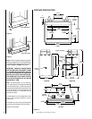
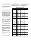
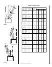
Measure height to the ceiling from the top of
fireplace-dimension “B.” Use the appropriate
Offset Elevation Chart to find dimension “A.”
Mark point where you will drive your nail to
show the center point for your offset ceiling cut.
Step 2. Proceed by using the Straight Up Instal-
lation Instructions for cutting and framing ceil-
ing and roof openings.
Note: See Framing and Dimension Chart for the
sizes of the ceiling and roof openings. The size
of the roof opening varies with the degree of
pitch of the roof.
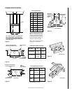
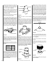
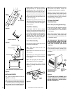
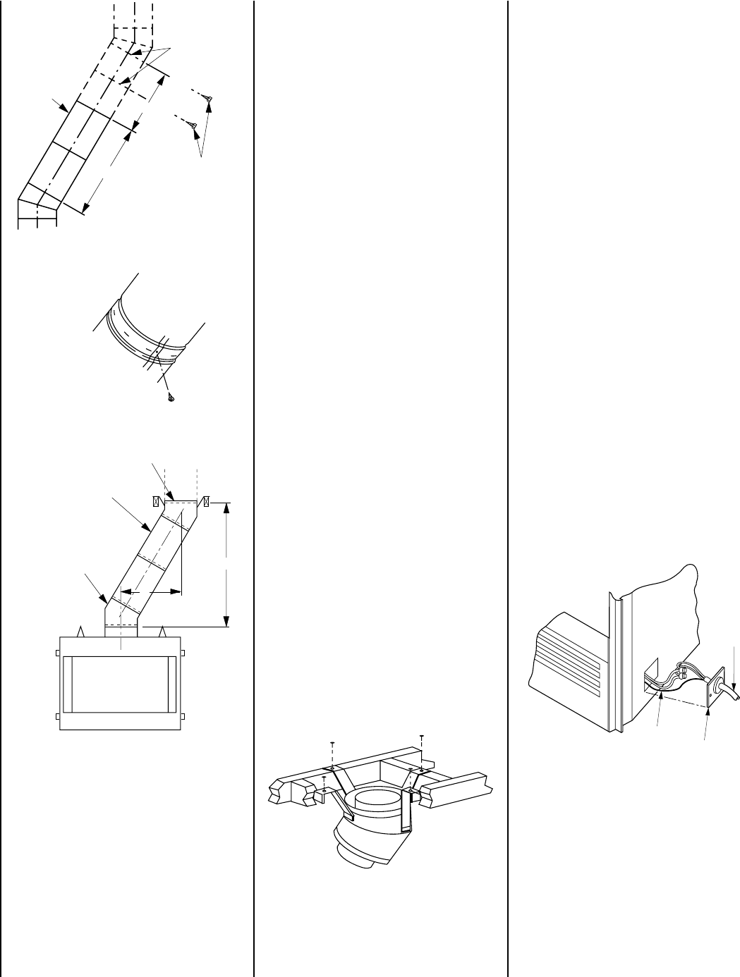
Offset Elbow Assembly
Offset elbows install the same as chimney
sections. First, snap the inner section INTO the
preceding inner section of flue. Check connec-
tion by pulling up slightly to ensure a tight fit.
Next, the outer sections snap lock OVER the
preceding outer section of chimney. Again,
check outer section by pulling up slightly to
ensure proper connection is made.
Return Elbow Assembly
Return elbows install the same way as round
terminations and stabilizers:
Step 1. Hold return elbow over top of last
chimney section.
Step 2. Center inner slip section into inner flue
pipe-slip down.
Step 3. Center outer-locking section over outer
chimney pipe. Push down until locking joint has
firmly engaged.
Step 4. Pull up slightly on return elbow to
ensure locking joint has firmly engaged.
Step 5. Secure support straps to framing
members by nailing under tension in sheer
(
Figure 42
).
Figure 39
Figure 40
Figure 41
Chimney
Section
Joints
No. 8 x 1/2" SMS
Screws Required At
Every Joint Past 6'
No Screws Required In
Joints For First 6' of Offset
4'
6'
Underside Of Chimney
Chimney Section (S)
FTF8-E30 Return Elbow*
FTF8-30 Offset Elbow*
B
A
*Part of Offset/Return Package Model FTF8-ES30
Return
Elbow
Note: The return elbow assembly performs the
same function as a stabilizer. Consider this
when determining the need for a stabilizer.
Note: Do not apply excessive pressure to any
subsequent chimney section following return
elbow assembly when installing. Ensure that
each subsequent chimney section is securely
attached by testing as noted above.
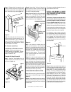
OPTIONAL EQUIPMENT
CONSIDERATIONS
Blower Kits (Circulating Models Only)
Blower Kits model FBK-100/200 are available
for use with circulating models. The Blower
Kit can be installed prior to or after installation
of the fireplace.
Note: These fireplace models require a wall
switch for fan operation. Refer to the installa-
tion instructions included with the Blower Kits
for installation details.
THE FIREPLACE MUST BE WIRED TO THE
HOUSE ELECTRICAL SYSTEM AT THE TIME
OF INSTALLATION IN ORDER FOR THE OP-
TIONAL FANS TO OPERATE, (SEE
FIGURES
43 AND 44
).
Note: The utilization of fans will increase the
air flow around the firebox. However, only a
minimal increase in heat output should be
anticipated.
INSTALLING OFFSETS
First, review the Offset Elevation Chart and
Figure 41
for reference.
Step 1. Determine the offset distance where chim-
ney is to pass through the first ceiling-dimension
“A.” To find this point on your ceiling, first deter-
mine the center point for a vertical chimney fol-
lowing the instructions for vertical installation.
Figure 42