


Special offers from our partners!

Find Replacement BBQ Parts for 20,308 Models. Repair your BBQ today.

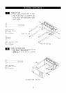
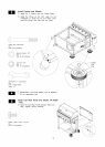
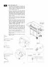
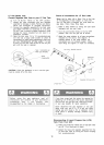
Install Side Burner Kit
[] Insert the Side burner Gas Valve Assembly into
Side Burner Tube (See Figure 1). Be sure the
orifice is inside the Burner Tube properly (see
warning on Page 3), or lighting the burner may
cause explosion and/or fire.
[]
[]
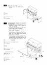
Insert the Side Burner Gas Valve Assembly
through the Side Burner Gas Valve Hole on the
Side Burner Frame. Align the 2 holes on the
Side Burner Frame with the threaded holes on
the Side Burner Gas Valve Bracket. Then insert
the two (2) screws and washers provided and
tighten securely.
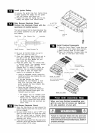
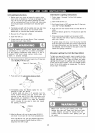
Fasten the Control Knob onto the Side Burner
Gas Valve Stem. Be sure that the OFF position
faces the Burner.
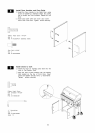
[] Connect the Electric Wire terminal from Side
Burner with the other from Grill Head as shown.
Bind the connected Electric Wire and Side
Burner Connection Tube together using the
supplied Fastening Band.(Note: located in
Operator's Manual plastic bag).
[]
[]
[]
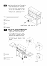
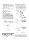
The gap between the Side Burner Electrode Tip
and the Side Burner Port should be
approximately 1/8"~ 3/16". If the gap is wider
than 3/16", use a pair of long nose pliers and
gently bend the Electrode Tip toward the burner.
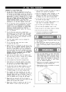
Cut and remove Fastening Band from Side
Burner and Pot Support before use.
Place the Side Burner Pot Support into the Side
Burner Frame.
[] Place the Side Burner Wind Shield on the Side
Burner Frame.
Side Burner
Pot Support
Pattern Head Screw M4x8mm
Qty. 2
Part # $132M04082
©
Plain Washer M4
Qty. 2
Part # S411M04122
Electrical connection
Figure
Control Knob for Side Burner
Qty. 1
Part # P03426083H
Scale 1:2
Fastening Band
Qty. 1
15
1/8.~3/16. BURNER
PORT