


Special offers from our partners!

Find Replacement BBQ Parts for 20,308 Models. Repair your BBQ today.

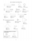
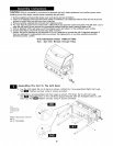
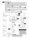
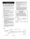
_r_ Installing Side Burner Kit
1. Attach the Side Burner Gas Valve Assembly to the Side Burner Gas Valve Hole on the Side Burner
Frame. See _ Align the 2 holes on the Side Burner Frame with the threaded holes on the
Side Burner Gas Valve Bracket. Tighten securely using 2 screws and washers provided.
2. Cut Fastening Band from Pot Support and set Pot support aside. Install the Side Burner through
the top hole in Side Burner Frame and onto the Side Burner Gas Valve. Make sure that opening
at end of Side Burner Connection Tube goes over tip of Side Burner Gas Valve. Secure Side Burner
with supplied Cotter Pin. See
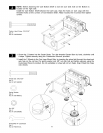
3. Install the Control Knob to the Side Burner Gas Valve Stem. See m
4. Connect the Electric Wire terminal from Side Burner with the other from Grill Head. See
Bind the connected Electric Wires and Side Bumer Connection Tube together using the supplied Fastening
Band.
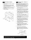
5. The gap between the Side Burner Electrode Tip and the Side Burner Port should be approximately
1/8"-3/16". See I_J"_I If the gap is wider than 3/16", use a pair of long nose pliers and gently
bend the Electrode Tip toward the burner.
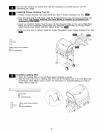
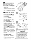
6. Place the Side Burner Pot Support into the Side Burner Frame. See W
_Ji:l
7. Place the Side Burner Wind Shield on the Side Burner Frame. See
llra.-"l
Pattern Head Screw M4x8mm
Qty. 2
Ref. # S132MO4082
Plain Washer M4
Qty. 2
Ref. # S411M04122
\
Control Knob
Qty. 1
Ref. # P03426061C
SIDE 1/ _I_3/ BURNER
BURNEI__
ELEC-
TRODE
Cotter Pin
Qty. 1
Ref. # P05501010B
Fastening Band
Qty. 1
Ref. # P055340011
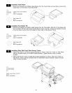
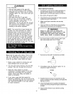
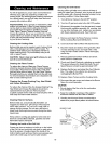
• When you have finished
assembling your grill we
strongly urge that all Pat-
tern Head Thumb Screws
be tightened, either with
the supplied Tightening
Tool or a #2 Phillips Head
Screwdriver
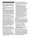
Be sure the Electric Wire and Regulator
Hose are bound together and fixed to the
hole on the top of Right Cart Side Panel.
14