Special offers from our partners!

Find Replacement BBQ Parts for 20,308 Models. Repair your BBQ today.
Operator’s Manual 11
Preparation
HOSE AND REGULATOR
John Deere models are equipped with a hose and regulator with a
QCC
®
-1 Quick Closing Coupling.
The QCC
®
coupling contains a magnetic Flow Limiting Device which
will limit the ow of gas should there be a leak between the regulator
and the appliance valve. This device will activate if the cylinder valve
is opened while the appliance valves are open. Be sure the appliance
valves are off before the cylinder valve is opened to prevent
accidental activation.
The QCC
®
coupling incorporates a heat sensitive hand wheel that will
cause the back check module in the QCC
®
cylinder valve to close when
exposed to temperatures between 240° and 300°F. Should this occur,
do not attempt to reconnect the nut. Remove hose/regulator assembly
and replace with a new one.
The pressure regulator is set at 11 inches WC (water column) and is
for use with LP gas only. The hose and hose couplings comply with
CGA Standard CAN 1.83. No modications or substitutions should be
attempted.
Protect the hose from dripping grease and DO NOT allow the hose to
touch any hot surface, including the base casting of the grill.
Inspect seal in the QCC
®
cylinder valve when replacing LP gas cylinder
or once per year whichever is more frequent. Replace seal if there is
any indication of cracks, creases, or abrasion.
Inspect hose before each use of the grill. If the hose is cracked,
cut, abraded or damaged in any way, the appliance must not be
operated.
For repair or replacement of hose/regulator assembly, contact your
dealer or approved service center.
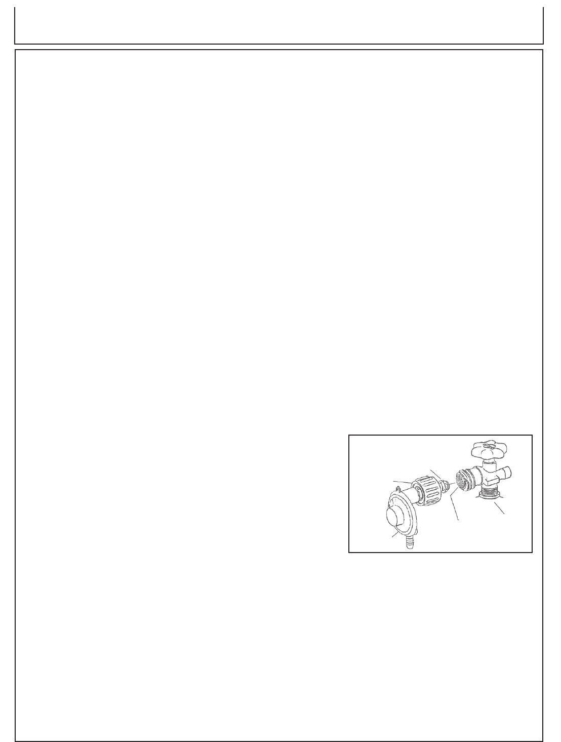
CONNECTING REGULATOR TO LP-GAS CYLINDER:
1. Be sure cylinder valve and appliance valves are “OFF’.
2. Place full LP-Gas Cylinder on base mounting lip and secure top
collar as per assembly instructions.
3. Center the nipple in the cylinder valve and hold in place.
Using other hand, turn the hand wheel clockwise until there is
a positive stop. Do not use tools. Hand tighten only. When
making the connection, hold the regulator in a straight line with
the cylinder valve, so as not to cross thread the connection.
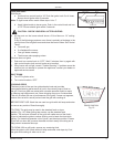
(Fig. 3)
4. Leak test connections. See “Leak Testing”.
5. Refer to lighting instructions. To avoid activating the Flow
Limiting Device when lighting, open cylinder valve slowly with
the appliance valves off. If the Flow Limiting Device is
accidentally activated, turn off cylinder valve and appliance
valves, wait 10 seconds to allow the device to reset, open
cylinder valve slowly, then open the appliance valve.
Nipple with Flow
Limiting Device
Heat Sensitive
Hand-Wheel
Regulator
Check
Valve
Cylinder
Shut-Off
Valve
Fig. 3


