


Special offers from our partners!

Find Replacement BBQ Parts for 20,308 Models. Repair your BBQ today.

GAS CONNECTION
ONLY USE THE REGULATOR AND HOSE ASSEMBLY PROVIDED WITH THIS GRILL.
REPLACEMENT PRESSURE REGULATORS AND HOSE ASSEMBLIES MUST BE
THOSE SPECIFIED BY THE MANUFACTURER.
This is a L.P. (Liquefied Petroleum Gas) configured grill. Do not attempt to use a natural gas supply
unless the grill has been reconfigured for natural gas use.
The installation of this appliance must conform with local codes or, in the absence of local codes, with
the National Fuel Gas Code, ANSI Z223. 1, or CAN/CGA-B149.2 Propane Installation Code.
L.P. tank Requirements:
The L.P. tank used with your grill must meet the following requirements:
1. Measurement: 12’’(30.5cm) (Diameter) X 18’’ (45.7cm) (Tall)
2. Maximum Capacity: 20lbs. (9Kg)
3. Constructed and marked in accordance with the specification for L.P.-gas cylinders of the U.S.
Department of Transportation (DOT) or the National Standard of Canada, CAN/CSA-B339,
Cylinders, Spheres and Tubes for the Transportation of Dangerous Goods. See L.P. tank collar
for marking.
4. Be arranged for vapor withdrawal.
5. Has a collar to protect the tank valve.
6. No dent or rust. A dented or rusty L.P. tank may be hazardous.
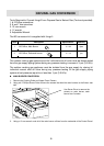
L.P. tank valve used must meet the following requirements:
1. Have type I outlet compatible with regulator provided.
2. Have safety relief valve.
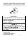
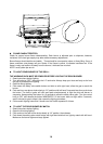
3. UL listed Overfill Protection Device (OPD), This OPD safety feature is identified by a unique
triangular hand wheel. Only use tanks equipped with this type of valve. (as the figure shown
below)
For your safety:
Ensure that the black plastic grommets of the regulator provided are in place and that the hose does not
come into contact with the heat shield or the grill head.
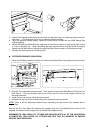
Connect the regulator to the L.P. tank:
VERY IMPORTANT:
a. THE REGULATOR SHALL INCORPORATE IN SUCH A LOCATION THAT IT WILL NOT ATTAIN A
TEMPERATURE ABOVE 140℉(60℃).
b. THE REGULATOR SHALL INCORPORATE A PRESSURE RELIEF VALVE OR OVERPRESSURE
DEVICE.
c. THE INLET OF THE PRESSURE REGULATOR SHALL BE FITTED TO CONNECT THE TYPE I
CONNECTION OF THE TANK VALVE PER ANSIZ21.81.
1. Make sure tank valve is in its full off position (turn clockwise to stop).
2. Check tank valve to assure it has proper external male threads (type I connection per ANSIZ21.81).
3. Make sure all burner knobs are in their off position.
4. Remove the protective cap from L.P. tank valve, Always use cap and strap supplied with valve.
5. Inspect valve connection port and regulator assembly. Look for any damage or debris. Remove any
debris. Inspect hose for damage. Never attempt to use damaged or plugged equipment. Contact
your local L.P. gas dealer for repair.
7