


Special offers from our partners!

Find Replacement BBQ Parts for 20,308 Models. Repair your BBQ today.

33
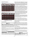
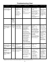
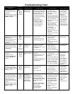
Troubleshooting Chart
Fault Description(s)
Symptoms of Abnormal
Operation
4
4 FLASHES
Associated
LED Code
2
• Circulator blower runs
continuously. No furnace
operation.
• Integrated control module
diagnostic LED is flashing
FOUR (4) flashes.
7
7 FLASHES
• Normal furnace
operation.
• Integrated control
module diagnostic LED
is flashing SEVEN (7)
flashes.
• Furnace fails to operate.
• Integrated control module
diagnostic LED is flashing
continuously.
C
CONTINUOUS
FLASHING
• Primary limit
circuit is open.
• Polarity of 115
volt power is
reversed.
• Flame sense
microamp signal is
low.
• Insufficient conditioned air
over the heat exchanger.
Blocked filters, restrictive
ductwork, improper
circulator blower speed,
or failed circulator blower.
• Flame rollout.
• Misaligned burners,
blocked flue and/or air
inlet pipe, or failed
induced draft blower.
• Loose or improperly
connected wiring.
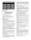
Possible Causes Corrective Action Cautions and Notes
• Check filters and
ductwork for blockage.
Clean filters or remove
obstruction.
• Check circulator blower
speed and performance.
Correct speed or replace
blower if necessary.
• Check burners for proper
alignment.
• Check flue and air inlet
piping for blockage,
proper length, elbows,
and termination. Correct
as necessary.
• Check induced draft
blower for proper
performance. Replace, if
necessary.
• Tighten or correct wiring
connection.
• Turn power OFF
prior to repair.
• See Product Data
Bulletin for
allowable rise
range and proper
circulator speed.
See “Vent/Flue
Pipe” section for
piping details.
• Replace pressure
switch with proper
replacement part.
• Polarity of 115 volt AC
power to furnace or
integrated control module
is reversed.
• Poor unit ground.
• Flame sensor is coated/
oxidized.
• Flame sensor incorrectly
positioned in burner
flame.
• Lazy burner flame due to
improper gas pressure or
combustion air.
• Review wiring diagram to
correct polarity.
• Verify proper ground.
Correct if necessary.
• Check and correct wiring.
• Sand flame sensor is
coated/oxidized.
• Inspect for proper sensor
alignment.
• Check inlet air piping for
blockage, proper length,
elbows, and termination.
• Compare current gas
pressure to rating plate
info. Adjust as needed.
• Turn power OFF
prior to repair.
• Turn power OFF
prior to repair.
• Sand flame
sensor with
emery clot.
• See “Vent/Flue
Pipe” section for
piping details.
• See rating plate
for proper gas
pressure.
• Inspect
pressure
switch
hose.
Repair, if necessary.
• Inspect flue and/or inlet
air piping for blockage,
proper length, elbows,
and termination.
Check
drain
system.
Correct
as
necessary.
• Correct pressure switch
setpoint or
contact
motion.
• Tighten
or
correct
wiring
connection.
9
9 FLASHES
• Furnace not operating.
• Integrated control module
diagnostic LED is flashing
EIGHT (8) flashes.
• Furnace operating on
low stage gas with high
stage induced draft blower
• High stage circulator
blower (temperature, of
conditioned air, lower than
typical).
• Integrated control module
diagnostic LED is flashing
NINE (9) flashes.
8
8 FLASHES
• High stage
pressure switch
circuit does not
close in response
to high stage
induced draft
blower operation.
• Problem with
igniter circuit.
• Improperly
connected igniter
• Bad igniter
• Poor unit ground
• Pressure switch hose
blocked, pinched or
connected improperly.
• Blocked flue and/or inlet air
pipe, blocked drain system,
or weak induced draft
blower.
• Incorrect pressure switch
setpoint or malfunctioning
switch contacts.
• Loose or improperly
connected wiring.
• Check and correct wiring
from integrated control
module to igniter
• Replace bad igniter
• Check and correct unit
ground
wiring
• Turn power OFF
prior to repair.
• Replace igniter
with proper
silicon nitride
replacement part.
• Turn power OFF
prior to repair.
• Replace pressure
switch with
proper
replacement part.
• Integrated control module
diagnostic LED is flashing
FIVE (5) times.
• Induced draft blower and
circulator blower run
continuously. No furnace
operation.
• Flame sensed with
no call for heat.
• Correct short at flame
sensor or in flame
sensor wiring.
• Check for lingering
flame
• Verify proper operation
of gas valve
• Short to ground in flame
sense circuit.
• Lingering burner flame.
• Slow closing gas valve
• Turn power OFF
prior to repair.
5
5 FLASHES