


Special offers from our partners!

Find Replacement BBQ Parts for 20,308 Models. Repair your BBQ today.
18
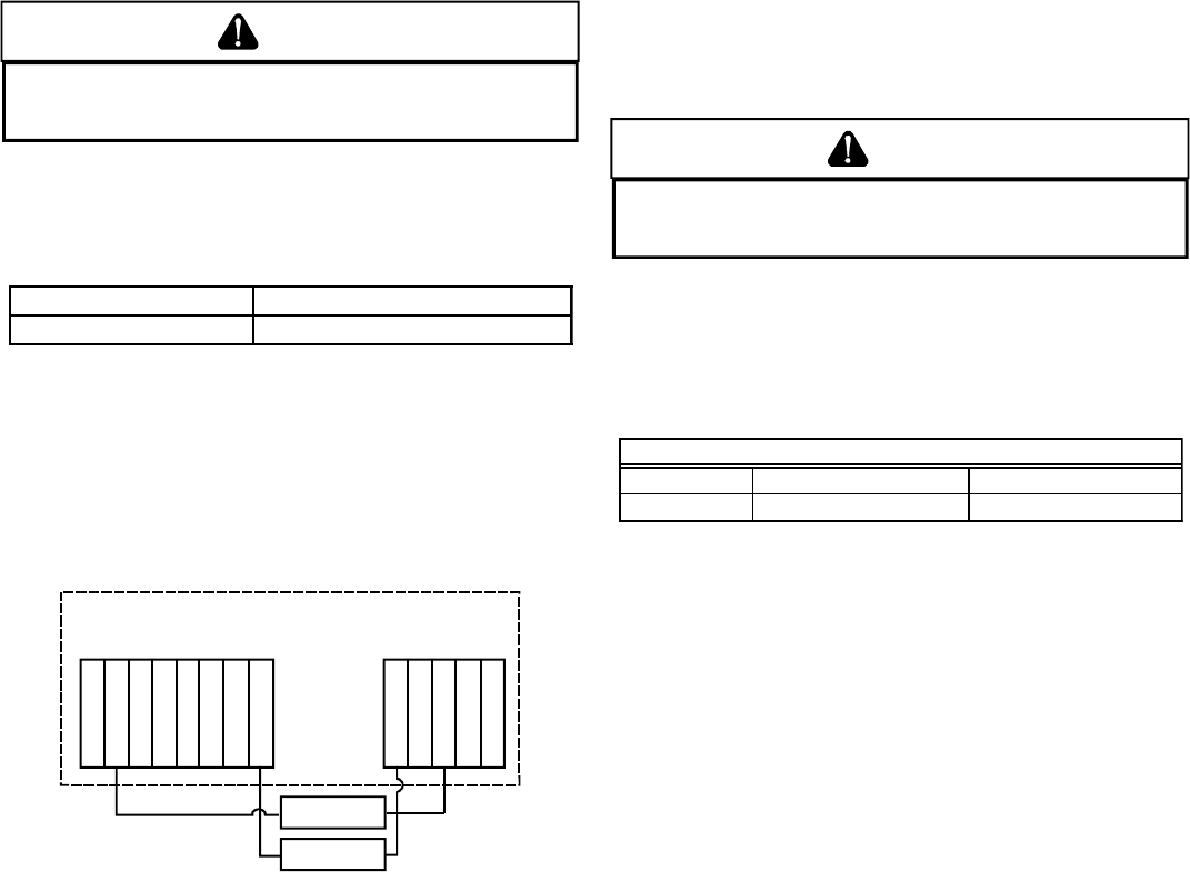
115 VOLT LINE CONNECTION OF ACCESSORIES (HUMIDIFIER
AND
E LECTRONIC A IR C LEANER)
WARNING
T
O AVOID PERSONAL INJURY, ELECTRICAL SHOCK OR DEATH, DISCONNECT
ELECTRICAL POWER BEFORE SERVICING OR CHANGING ANY ELECTRICAL
WIRING.
The furnace integrated control module is equipped with line voltage
accessory terminals for controlling power to an optional field-
supplied humidifier and/or electronic air cleaner.
The accessory load specifications are as follows:
Humidifier 1.0 Amp maximum at 120 VAC
Electronic Air Cleaner 1.0 Amp maximum at 120 VAC
Turn OFF power to the furnace before installing any accessories.
Follow the humidifier or air cleaner manufacturers’ instructions
for locating, mounting, grounding, and controlling these
accessories. Accessory wiring connections are to be made
through the 1/4" quick connect terminals provided on the furnace
integrated control module. The humidifier and electronic air
cleaner hot and neutral terminals are identified as HUM and EAC.
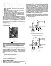
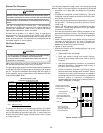
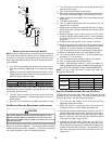
All field wiring must conform to applicable codes. Connections
should be made as shown in the following illustration.
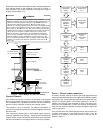
EAC
Line
Transformer
Hum
Line
Transformer
EAC
Hum
Air Cleaner
Humidifier
Control Module
Hot 120 VAC
Neutral 120 VAC
Optional
Accessories
{
Figure 15 - Accessories Wiring
If it is necessary for the installer to supply additional line voltage
wiring to the inside of the furnace, the wiring must conform to all
local codes, and have a minimum temperature rating of 105°C.
All line voltage wire splices must be made inside the furnace
junction box.
The integrated control module humidifier terminals (HUM) are
energized with 115 volts whenever the induced draft blower is
energized. The integrated control module electronic air cleaner
terminals (EAC) are energized with 115 volts whenever the
circulator blower is energized.
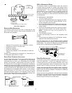
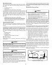
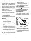
24 VAC HUM
1. 24 VAC Hum - A ¼” insulated male quick connect terminal
on the pressure switch provides 24 VAC humidifier control.
this terminal will be powered any time the pressure switch
is closed. To connect 24 VAC hum, connect 24vac line of
humidifier to piggyback on the pressure switch. The com
side of the humidfier to C on the terminal strip on the control
board (or to com side to 24VAC transformer). Do not
connect 115V humidifier to these terminals.
IX. GAS SUPPLY AND PIPING
GENERAL
The furnace rating plate includes the approved furnace gas input
rating and gas types. The furnace must be equipped to operate
on the type of gas applied. This includes any conversion kits
required for alternate fuels and/or high altitude.
CAUTION
T
O PREVENT UNRELIABLE OPERATION OR EQUIPMENT DAMAGE, THE INLET
GAS SUPPLY PRESSURE MUST BE AS SPECIFIED ON THE UNIT RATING PLATE
WITH ALL OTHER HOUSEHOLD GAS FIRED APPLIANCES OPERATING.
Inlet gas supply pressures must be maintained within the ranges
specified in the following table. The supply pressure must be
constant and available with all other household gas fired
appliances operating. The minimum gas supply pressure must
be maintained to prevent unreliable ignition. The maximum must
not be exceeded to prevent unit overfiring.
Natural Gas
Minimum: 5.0" w.c. Maximum:10.0" w.c.
Propane Gas
Minimum: 11.0" w.c. Maximum:13.0" w.c.
Inlet Gas Supply Pressure
NOTE: Adjusting the minimum supply pressure below the limits
in the above table could lead to unreliable ignition. Gas input to
the burners must not exceed the rated input shown on the rating
plate. Overfiring of the furnace can result in premature heat
exchanger failure. Gas pressures in excess of 13 inches water
column can also cause permanent damage to the gas valve.
At all altitudes, the manifold pressure must be within 0.3 inches
w.c. of that listed in the Product Data Book applicable to your
model* for the fuel used. At all altitudes and with either fuel, the air
temperature rise must be within the range listed on the furnace
nameplate. Should this appliance be converted to LP, refer to the
instructions included in the factory authorized LP conversion kit
LPT-03B .
HIGH A LTITUDE D ERATE
IMPORTANT NOTE: The furnace will naturally derate itself with
altitude. Do not attempt to increase the firing rate by changing
orifices or increasing the manifold pressure. This can cause poor
combustion and equipment failure.
When this furnace is installed at high altitude, the appropriate
High Altitude orifice kit must be applied. The furnace is supplied
with orifices sized for natural gas at altitudes up to 4,500 feet
using a heating value of approximately 1,000 Btu/hr, and should
not normally require change. Most cases will not require a change
at altitudes up to 7,500 feet. For use at altitudes in excess of 4,500
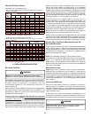
feet, refer to the following table for maximum input rates based on
altitude. Contact your local gas utility for the heating value of the
gas. Refer to the National Fuel Gas Code ANSI Z223.1 and the
following section to calculate firing rates.