


Special offers from our partners!

Find Replacement BBQ Parts for 20,308 Models. Repair your BBQ today.
17
G
Y
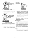
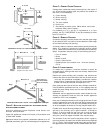
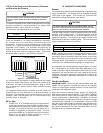
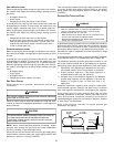
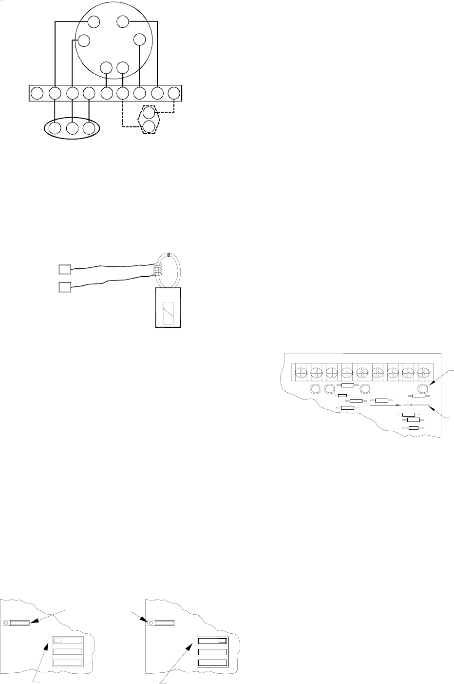
Two-Stage Heating with Two-Stage Cooling
R
B/C G R W1 W2O
YLO
Y
DEHUM
TWIN
NEU
HOT
Furnace Integrated
Control Module
Thermostat
Two-Stage Heating
with
Two-Stage Cooling
()
Remote
Condensing Unit
(Two-Stage Cooling)
Dehumidistat
[Optional]
Y C
YLO
YLO W2
W1
Thermostat Diagrams
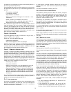
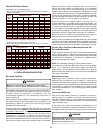
SETTING THE H EAT A NTICIPATOR
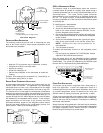
The following method should be used in measuring the amp
draw of the control circuit to assure proper adjustment of the
thermostat heat anticipator
R
R
• Wrap the “R” leg around a clip-on amp meter 10 times.
• Energize the furnace in the heat mode.
• Record the reading.
• Divide this reading by 10.
• Set the heat anticipator on the thermostat to match this
reading.
Example: If the reading on the amp meter is “4”, divide this by 10.
The anticipator setting will be .4 amps.
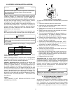
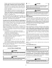
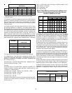
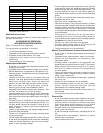
SINGLE-STAGE T HERMOSTAT A PPLICATION
A single-stage thermostat with only one heating stage can be
used to control this furnace. The application of a single-stage
thermostat does not offer “true” thermostat-driven two-stage
operation, but provides a timed transition from low to high fire.
The furnace will run on low stage for a fixed period of time before
stepping up to high stage to satisfy the thermostat’s call for heat.
The delay period prior to stepping up can be set at either 5 or 10
minutes through the DIP switch adjacent to the Heat Off delay
DIP switches on the integrated control module. To use a single-
stage thermostat, turn off power to the furnace, move the
thermostat selection jumper on the integrated control module
from the “two-stage” position to the “single-stage” position, turn
power back on. Refer to the following figures.
3
2
1
T
W
O
S
I
N
G
L
E
TSTAT
OFF
3
2
1
T-Stat selection jumper in
single-stage thermostat
position.
DIP switch position 3: ON
Delay Period: 10 minutes.
DIP switch position 3: OFF
Delay Period: 5 minutes.
T
W
O
S
I
N
G
L
E
TSTAT
ON
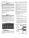
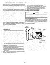
24 VOLT D EHUMIDISTAT W IRING
The optional usage of a dehumidistat allows the furnace’s
circulator blower to operate at a slightly lower speed during a
combined thermostat call for cooling and dehumidistat call for
dehumidification. This lower blower speed enhances
dehumidification of the conditioned air as it passes through the
AC coil. For proper function, a dehumidistat applied to this
furnace must operate on 24 VAC and utilize a switch which opens
on humidity rise.
To install/connect a dehumidistat:
1. Turn OFF power to furnace.
2. Secure the dehumidistat neutral wire (typically the white
lead) to the screw terminal marked “DEHUM” on the
furnace integrated control module.
3. Secure the dehumidistat hot wire (typically the black lead)
to the screw terminal marked “R” on the furnace integrated
control module.
4. Secure the dehumidistat ground wire (typically the green
lead) to the ground screw on the furnace junction box.
NOTE: Ground wire may not be present on all
dehumidistats.
5. Turn ON power to furnace.
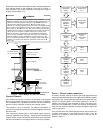
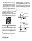
To enable the dehumidify function on the integrated control
module:
1. Cut the jumper wire labeled “CUT FOR DEHUM” located
adjacent to the DEHUM screw terminal.
Once the jumper wire is cut, the dehumidify function is enabled
during a combination call for cooling (T-Stat) and dehumidification
(Dehum-Stat). The yellow LED adjacent to the DEHUM screw
terminal will be illuminated during dehumidification.
0 YL0 Y B/C G R W1 W2
TWIN
DEHUM
CUT FOR
DEHUM
0YL0YB/CGRW1W2
CR35
R122
R128
W3
DS7 R191
R85
DS3
R84
R22
DS4 DS5
TP1
TP2
DEHUMIDIFICATION
LED (YELLOW)
DEHUMIDIFICATION
JUMPER WIRE
(CUT TO ENABLE)
W14
FOSSIL F UEL APPLICATIONS
This furnace can be used in conjunction with a heat pump in a
fossil fuel application. A fossil fuel application refers to a
combined gas furnace and heat pump installation which uses
an outdoor temperature sensor to determine the most cost
efficient means of heating (heat pump, gas furnace, or both).
A heat pump thermostat with three stages of heat is required to
properly use a two-stage furnace in conjunction with a heat pump.
Refer to the fossil fuel kit installation instructions for additional
thermostat requirements.
Strictly follow the wiring guidelines in the fossil fuel kit installation
instructions. All furnace connections must be made to the furnace
two-stage integrated control module and the “FURNACE”
terminal strip on the fossil fuel control board.