


Special offers from our partners!

Find Replacement BBQ Parts for 20,308 Models. Repair your BBQ today.

32
1
Integrated control module will automatically attempt to reset from lockout after one hour.
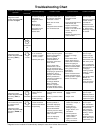
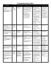
Troubleshooting Chart
• Furnace lockout due
to an excessive
number of ignition
“retries” (3 total)
1
.
• Auxiliary limit open
• Locate and correct gas
interruption.
• Replace or realign
igniter.
• Check flame sense
signal. Sand sensor if
coated and/or oxidized.
• Check flue piping for
blockage, proper length,
elbows, and termination.
• Verify proper induced
draft blower
performance.
• Check circulator blower
speed and performance.
Correct speed or replace
blower if necessary.
• Turn power OFF
prior to repair.
• Igniter is fragile,
handle with care.
• Sand flame sensor
with emery cloth.
• See “Combustion
and Ventilation Air
Requirements” and
“Category I
Venting (Vertical
Venting)” section
for details.
• See Product Data
Bulletin for
allowable rise
range and proper
circulator speed.
• Furnace fails to operate.
• Integrated control
module diagnostic LED
is flashing ONE (1)
flash.
1
1 FLASH
• Failure to establish flame.
Cause may be no gas to
burners, bad igniter or
igniter alignment,
improper orifices, or
coated/oxidized or
improperly connected
flame sensor.
• Loss of flame after
establishment. Cause
may be interrupted gas
supply, lazy burner flames
(improper gas pressure or
restriction in flue or
improper induced draft
blower performance.
• Insufficient conditioned
air over the heat
exchanger. Blocked
filters, restrictive
ductwork, improper
circulator blower speed,
or failed circulator blower.
• Low stage pressure
switch circuit is
closed.
• Induced draft blower
is not operating.
• Replace induced draft
blower pressure
switch.
• Repair short.
• Turn power OFF
prior to repair.
• Replace pressure
switch with proper
replacement part.
• Furnace fails to operate.
• Integrated control
module diagnostic LED
is flashing TWO (2)
flashes.
2
2 FLASHES
• Induced draft blower
pressure switch contacts
sticking.
• Shorts in pressure switch
circuit.
• Inspect pressure
switch hose. Repair, if
necessary,
• Inspect flue for
blockage, proper
length, elbows, and
termination.
• Correct pressure
switch setpoint or
contact motion.
• Tighten or correct
wiring connection.
• Pressure switch hose
blocked, pinched or
connected improperly.
• Blocked flue or weak
induced draft blower.
• Incorrect pressure switch
setpoint or malfunctioning
switch contacts.
• Loose or improperly
connected wiring.
• Pressure switch
circuit not closed.
• Induced draft blower
is operating.
• Induced draft blower
runs continuously with
no further furnace
operation.
• Integrated control
module diagnostic LED
is flashing THREE (3)
flashes.
3
3 FLASHES
• Turn power OFF
prior to repair.
• See “Combustion
and Ventilation Air
Requirements”
and “Category I
Venting (Vertical
Venting)” section
for details.
• Replace pressure
switch with proper
replacement part.
• No 115 volt power
to furnace, or no 24
volt power to
integrated control
module.
• Blown fuse or
circuit breaker.
• Intergrated contol
module has an
internal fault
• Manual disconnect switch
OFF, door switch open, or
24 volt wires improperly
connected or loose.
• Blown fuse or circuit
breaker.
• Intergrated contol module
has an internal fault
• Assure 115 and 24 volt
power to furnace
integrated control
module.
• Check integrated control
module fuse (3A).
Replace if necessary.
• Check for possible
shorts in 115 and 24 volt
circuits. Repair as
necessary.
• Replace bad intergrated
control module.
• Turn power OFF
prior to repair.
• Replace integrated
control module
fuse with 3A
automotive fuse.
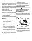
• Read precautions
in “Electrostatic
Discharge” section
of manual.
• Furnace fails to operate.
• Integrated control
module diagnostic LED
provides no signal.
NONE
Fault Description(s) Possible Causes Corrective Action Cautions and Notes
Symptoms of Abnormal
Operation
Associated
LED Code
2
• LED is steady ON.
ON
CONTINUOUS
ON
• Normal operation.
• Normal operation.
• None.
• Normal operation.