


Special offers from our partners!

Find Replacement BBQ Parts for 20,308 Models. Repair your BBQ today.
5
www.ultrachefgrills.com
Propane Cylinder Installaon
Cylinder Connecon: Ensure that the gas regulator hose is kink free. Remove the cap or plug from the cylinder
fuel valve. Insert the black QCC1 regulator nipple onto the QCC1 fuel valve. Hand ghten clockwise. Do not use
tools. Leak test all joints prior to using the barbecue. A leak test must be performed annually, and each me a
cylinder is hooked up, or if a part of the gas system is replaced.
• Check that the cylinder valve is closed by turning the knob clockwise.
• Check that the grill’s burner knobs are in the o posion.
• Open cabinet doors.
• Place the cylinder into the tank holder in boom of shelf.
• Posion the cylinder so that the valve faces toward the front of the unit.
• Aach regulator hose.
WARNING!
Use only the pressure regulator and hose assembly provided with this barbecue. Replace
ment
pressure regulators and hose assemblies must be specied by the manufacturer. Do not store a spare
propane cylinder on the shelf beneath the barbecue. The regulator must be aached so that no part of the
hose touches the underside of the grill or drippan. A re will result if these direcons are ignored.
The regulator supplies a pressure of 11 inches. water column to the gas grill and has a QCC1 type ng. Cyl
inders
to be used with this unit must be supplied with a QCC1 cylinder valve. A QCC1 cylinder has a posive seat
ing
connecon, which will not allow gas ow unl a posive seal has been achieved. It is also equipped with an
excess ow device. In order to aain full ow to the grill, the valves must be in the o posion when the cylin
der
valve is turned on.
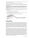
Natural Gas Hook-Up
This natural gas grill is supplied with a 10 supply hose (complete with a quick disconnect) designed for natural
gas and cered for outdoor use. The gas grill is designed to operate at an inlet pressure of 7 inches water
column. Piping and valves upstream of the quick disconnect are not supplied. The installaon must com
ply
with CAN B149.1 Natural Gas and Propane installaon code in Canada, or to the Naonal Fuel Gas Code,
ANSI Z223.1 in the United States. The gas supply pipe must be suciently sized to supply the BTU/h specied
on the rang plate, based on the length of the piping run. The quick disconnect must not be installed in an
upward direcon and a readily accessible manual shut-o valve must be installed upstream of, and as close to,
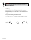
the quick disconnect as is feasible. The ared end of the hose must be connected to the ng on the end of
the ex tube as illustrated in the Natural Gas Hose Aachment diagram. Tighten using two wrenches. (Do not
use thread sealer/pipe dope.) These connecons must be made by a licensed gas installer. Leak test all joints
prior to using the gas grill.
WARNING!
• The installaon must be performed by a licensed gas er, and all connecons must be leak tested before
operang the grill.
• Do not route hose underneath drip pan.
• Do not route hose between space in boom shelf and back panel.
• Do not route hose over top of back panel.
• Ensure all hose connecons are ghtened using two wrenches. Do not use teon tape or pipe dope on
any hose connecon.
• Ensure the hose does not contact any high temperature surfaces, or it may melt and leak causing a re.
• Do not use enclosure to store excess hose, as there is a greater chance of the hose contacng a hot surface,
it may melt and leak causing a re.
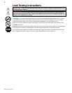
• Leak test all the connecons using a soap and water soluon, as per the leak tesng instrucons found in
the this manual.