


Special offers from our partners!

Find Replacement BBQ Parts for 20,308 Models. Repair your BBQ today.

22
!
!
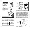
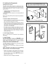
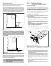
Wall Switch
You must use two wall switches with this unit. Position the
wall switch in the desired position on a wall. Run a maxi-
mum of 25 feet (7.8 m) or less length of 18 A.W.G. mini-
mum wire and connect it to the fireplace ON/OFF brown
switch wires.
WARNING: DO NOT CONNECT 110-120 VAC
TO THE WALL SWITCH OR THE CONTROL
VALVE WILL BE DESTROYED.
Wiring the Light
The light operates on 110-120 VAC. Position the wall switch
in the desired position on the wall. Connect 14 AWG mini-
mum wire to the black and white wires in the unit.
CAUTION: LABEL ALL WIRES PRIOR TO DISCONNEC-
TION WHEN SERVICING CONTROLS. WIRING ERRORS
CAN CAUSE IMPROPER AND DANGEROUS OPERA-
TION. VERIFY PROPER OPERATION AFTER SERVICING.
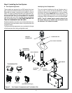
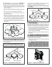
Intermittent Pilot Ignition (IPI) Wiring
3 Volt Transformer
This appliance comes with a 3 volt transformer found in the
manual bag. Plug the transformer leads to the green con-
trol module (see Figure 25). Then plug the transformer into
the “Trans” outlet on the junction box.
Appliance Requirements
This appliance requires that 110-120 VAC be wired to the
factory installed junction box. Maintain correct polarity when
wiring the junction box.
WARNING: DO NOT CONNECT 110-120 VAC
TO THE GAS CONTROL VALVE OR THE AP-
PLIANCE WILL MALFUNCTION AND THE
VALVE WILL BE DESTROYED.
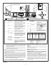
Optional Accessories
Optional remote control kits require that 110-120 VAC be
wired to the factory installed junction box before the fire-
place is permanently installed.
Heat-Zone kits are approved with this fireplace as heat
management accessories.
Multi-function wall switch (WSK-MLT) requires the PLUG-
ADP kit. Attach the black and white light wires to the plug
with two 1/4” electrical connectors. Plug the light into the
“AUX” cord on the WSK-MLT.
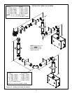
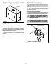
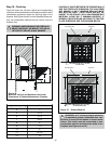
Step 9. Wiring the Fireplace
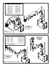
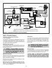
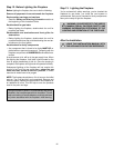
Figure 25. Intermittent Pilot Ignition (IPI) Wiring Diagram
NOTE 1: Ignition module, valve, pilot and wall switch operate on 3 volts.
NEUTRAL
GROUND
REMOTE
CONTROL
HOT
LOW VOLTAGE
SEE NOTE 1
ON/OFF
WALL SWITCH
VALVE
BROWN
BROWN
RED
ORANGE
GREEN
BLACK
OPTIONAL
BATTERY
BACK-UP
BLACK (IGNITOR)
BLACK (SENSOR)
BLACK
GROUND TO
FIREPLACE
CHASSIS
PILOT ASSEMBLY
AND VALVE ASSEMBLY
MUST BE GROUNDED
(COMMON GROUND
WITH FIREPLACE
CHASSIS)
SPARK TO
PILOT IGNITOR
IGNITOR
MODULE
3V
TRANSFORMER OUTLET
PLUG-IN
3V TRANSFORMER
FLAME SPARKER /
SENSOR
LOW VOLTAGE
SEE NOTE 1
OPTIONAL
BATTERY
BACK-UP
IGNITION
MODULE
(3V)
CONNECT TO LOW
VOLTAGE WALL SWITCH
TRANSFORMER
3V
BLACK
WHITE
Back light must be wired to a separate 110-120 VAC wall switch.