


Special offers from our partners!

Find Replacement BBQ Parts for 20,308 Models. Repair your BBQ today.

20
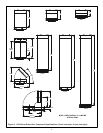
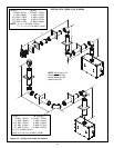
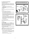
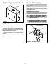
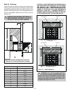
Step 5. Installing the Optional Heat-Zone Kit
Figure 23
Heat-Zone Kit
1. Remove the knockout from the top of the fireplace and
discard it (see Figure 23).
2. Center the duct collar around the exposed hole and at-
tach it to the fireplace with 3 screws. NOTE: Do this BE-
FORE final positioning of the fireplace.
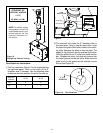
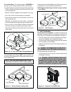
3. Determine the location for the air register/fan housing
assembly.
Reference the Heat-Zone kit instructions for the remaining
installations steps.
!
!
!
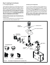
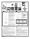
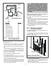
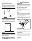
Step 6 The Gas Control System
WARNING: THIS UNIT IS NOT FOR USE WITH
SOLID FUEL.
The type of gas control system used with this model is
Intermittent Pilot Ignition.
Intermittent Pilot Ignition System
This system includes millivolt control valve, standing pilot,
thermopile/thermocouple flame sensor, and piezo ignitor.
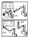
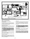
WARNING: 110-120 VAC MUST NEVER BE
CONNECTED TO A CONTROL VALVE IN A
MILLIVOLT SYSTEM.
WARNING: CONTINUOUS 110-120 VAC SER-
VICE MUST BE WIRED DIRECTLY TO THE FIRE-
PLACE JUNCTION BOX.
Figure 24. Gas Controls System
FLAME SENSOR
ROD
Intermittent Pilot Ignition
HEAT-ZONE
KNOCKOUTS