


Special offers from our partners!

Find Replacement BBQ Parts for 20,308 Models. Repair your BBQ today.

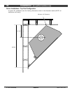
20 Installation (for qualified installers only)
© Travis Industries 4080214 100-01182_003
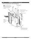
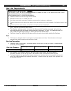
Wall Switch or Thermostat Installation
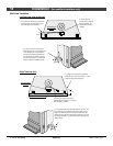
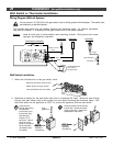
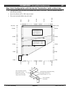
Wiring Diagram (Millivolt System)
Do not connect 110-120 VAC to the gas control valve or wiring system of this fireplace. The switch must
be installed by a qualified installer.
The included wall switch may be installed following the directions below. An optional thermostat
may also be installed. It is attached to the gas control valve in the same manner.
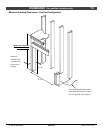
Caution: Label all wires prior to disconnection when servicing controls. Wiring errors can cause
improper and dangerous operation.
Orange
White
Piezo Igniter
Thermopile
Red
Thermocouple
Copper Co-Axial
Wire
Red
Spark Electrode
Pilot Hood
On/Off Switch (on fireplace)
Optional Wall Switch,
Thermostat, or
Remote Control
Brown
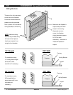
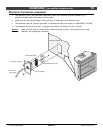
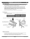
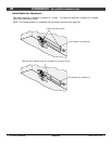
Wall Switch Installation
1. Attach the included wire to the gas control valve.
Attach the two wires to the top and
bottom posts on the gas control
valve (orientation does not matter).
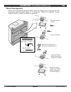
2. Determine a location for the wall switch (the wire is a maximum 25' long). Route the wire through
the gas inlet hole (either side) to the junction box and attach following the directions below. Set
the on/off switch on the appliance to "OFF" to control the appliance with the wall switch.
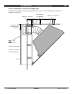
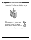
a
Carefully pack the wires into the
junction box. Attach the switch
to the junction box. Attach the
switchplate to the switch.
b
Standard
Screwdriver
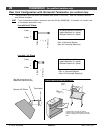
From
Appliance
Insert the wire
through the back of
the mounted
junction box (your
junction box may
look different).
Expose 1/2" of
each wire. Secure
the wires to the
posts on the side of
the on/off switch
(orientation does
not matter).
Standard
Screwdriver