


Special offers from our partners!

Find Replacement BBQ Parts for 20,308 Models. Repair your BBQ today.
www.desatech.com
111250-01E 23
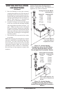
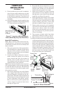
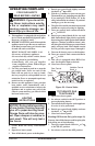
INSTALLING OPTIONAL WALL
MOUNT SWITCH - GWMS2
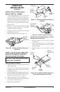
1. Connect one terminal of 25 ft. wire for wall
switch to TPTH terminal on the valve. Con-
nect remaining wire terminal to the TH termi-
nal on the valve. Make sure wire terminals are
in positions on unit as pictured in Figure 36.
If wires are not connected as shown, switch
will not work.
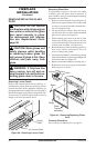
2. Route 25 ft. wire through openings provided
on sides of burner system to a convenient
location to mount your switch.
3. Connect one bare wire end to each terminal
of GWMS wall switch.
4. Install wall switch and cover in the wall.
FIREPLACE
INSTALLATION
Continued
Figure 36 - Attaching Alkaline Battery to
Receiver
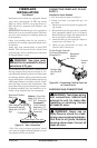
To Wall
Switch
Accessory
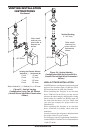
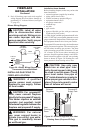
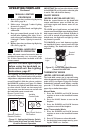
INSTALLING OPTIONAL WIRELESS
HAND-HELD REMOTE CONTROL
-
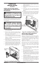
1. Open bottom louver and locate the switch
bracket on the left.
2. Unscrew the switch bracket. Lean bracket
forward so you are able to access the back of
the remote receiver.
3. Locate the battery clip mounted on the back of
the receiver. Slide a 9-volt alkaline battery (not
included) through the clip (see Figure 37).
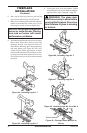
4. Attach the terminal wires to the battery.
5. Connect wires from receiver to TH and TPTH
to control valve (see Figure 38).
6. Replace the switch bracket.
To Wall
Thermostat
Figure 37 - Attaching Alkaline Battery to
Receiver
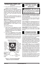
Figure 38 - Control Valve Terminals
To Optional
Remote
Accessory
9-Volt
Alkaline
Battery
Receiver
Terminal
Wires
Battery
Clip
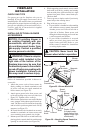
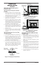
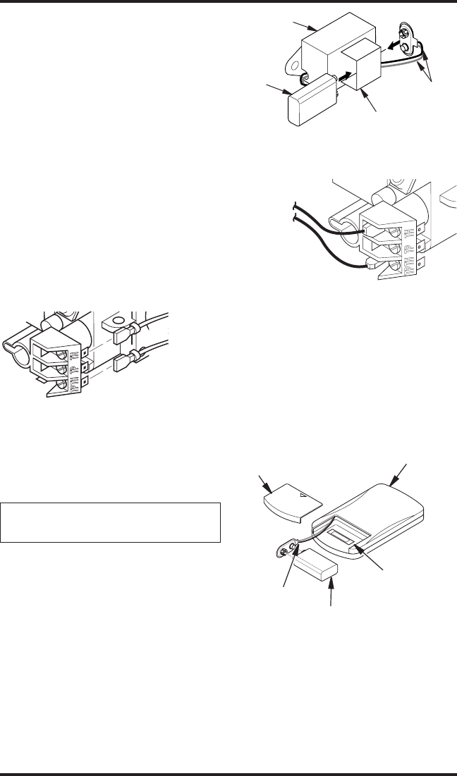
Held Remote Control Unit
1. Remove battery cover on back of remote
control unit.
2. Attach terminal wires to a 9-volt alkaline
battery (not included). Place battery into the
battery housing.
3. Replace battery cover onto remote control
unit.
Figure 39 - Installing Alkaline Battery in
Hand-Held Remote Control Unit
Battery
Cover
Battery
Housing
Remote
Control Unit
Terminal
Wires
9-Volt
Battery