


Special offers from our partners!

Find Replacement BBQ Parts for 20,308 Models. Repair your BBQ today.
107157-01F
8
For more information, visit www.desatech.com
For more information, visit www.desatech.com
INSTALLATION CLEARANCES
INSTALLATION
Continued
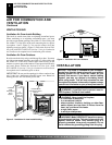
CONVENTIONAL FIREPLACE INSTALLATION
Conventional installation of this fireplace involves installing fire-
place along with the corner or cabinet mantel with hearth base
accessories against a wall in your home (see Accessories, page 22
and 23). Follow the instructions below to install the fireplace in this
manner.
Note:
The instructions below show installation using the cabinet
mantel and the G3000F/G3001U/G3004W/G3006F/G3007U se-
ries hearth base accessories. The hearth base accessory shown is
optional for this installation. You can install fireplace and cabinet/
corner mantel directly on the floor. The corner mantel accessory
cannot be installed with the G3000F/G3001U/G3004W/G3006F/
G3007U hearth base. The corner mantel can be paired with the
G3008F/G3009U/G3010F corner hearth base. If mounting fire-
place and cabinet or corner mantel to the floor, an optional G3005
Slim Base kit may be installed.
1. Assemble cabinet mantel, hearth base, and trim accessories.
Assembly instructions are included with each accessory.
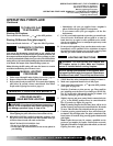
2. When installing blower, install a properly grounded, 120 volt
three-prong electrical outlet at fireplace location if an outlet is
not there. If possible, locate outlet so cabinet mantel will cover
it when installed (see Figure 9).
3. Install gas piping to fireplace location. This installation includes
an approved flexible gas line (if allowed by local codes) after
the equipment shutoff valve. The flexible gas line must be the
last item installed on the gas piping. See Installing Gas Piping
to Fireplace Location, pages 10 and 11.
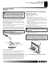
4. Place hearth base accessory against wall at installation loca-
tion. Cut an access hole in hearth top to run gas line to fire-
place (see Figure 9). Make sure to locate access hole so cabi-
net mantel will cover it when installed.
Note:
You can secure
base to floor using wood screws. Countersink screw heads and
putty over.
5. Route gas line through access hole in hearth base.
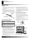
6. Center cabinet mantel on hearth base (see Figure 10, page 9).
Make sure mantel is flush against wall.
7. Break off nailing flanges (see Figure 11, page 9) with hammer
or pliers.
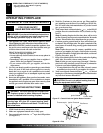
WARNING: Maintain the minimum clearances. If
you can, provide greater clearances from floor, ceil-
ing, and adjoining wall.
Carefully follow the instructions below. This will ensure safe
installation.
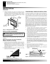
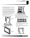
Minimum Clearances For Side Combustible
Material, Side Wall, and Ceiling
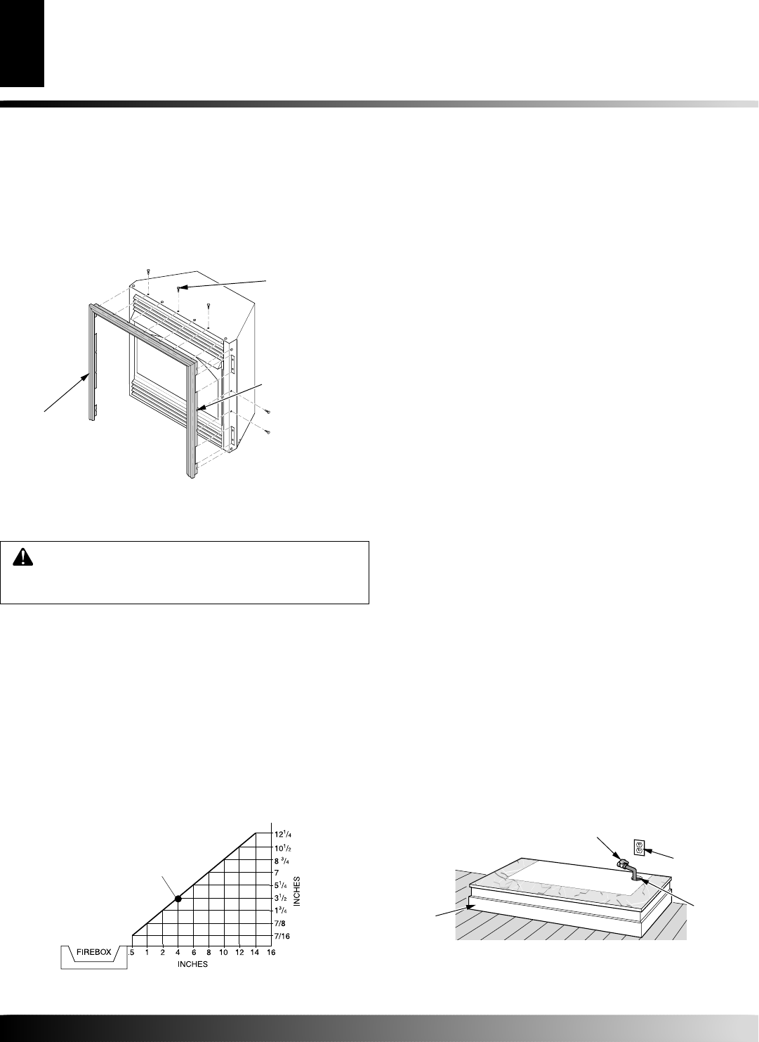
A. Clearances from the side of the fireplace cabinet to any com-
bustible material and wall should follow diagram in Figure 8.
Example:
The face of a mantel, bookshelf, etc. is made of
combustible material and protrudes 3
1
/2" from the wall. This
combustible material must be 4" from the side of the fireplace
opening (see Figure 8).
B. Clearances from the top of the fireplace opening to the ceiling
should not be less than 42 inches.
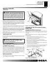
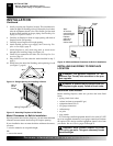
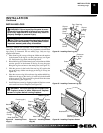
8. Tighten trim hanging screws (#10 x 6.25 shoulder) into holes
in cabinets. Place the assembled trim onto fireplace cabinet.
Align hanging notches on trim with hanging screws on side of
fireplace (see Figure 7). Push trim firmly into place, sliding
hanging notches over hanging screws.
INSTALLATION
Assembling and Attaching Optional Brass Trim (Cont.)
Installation Clearances
Conventional Fireplace Installation
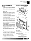
Figure 7 - Attaching Brass Trim to Fireplace
Trim
Hanging
Screws
Assembled
Brass Trim
Hanging
Notches
on Trim
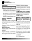
Figure 9 - Placing Hearth Base Accessory Against Wall
Figure 8 - Minimum Clearance for Combustible to Wall
*Minimum 16 inches from Side Wall
*
Example
Electrical
Outlet
Hearth
Base
Rigid Pipe and
Gas Shutoff Valve
Gas Line
Access
Hole