


Special offers from our partners!

Find Replacement BBQ Parts for 20,308 Models. Repair your BBQ today.
107157-01F
16
For more information, visit www.desatech.com
For more information, visit www.desatech.com
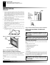
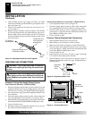
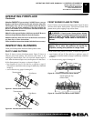
Locate the blower switch by opening lower louver on fireplace.
Blower switch is located at lower left inside louver door.
This thermostat-controlled blower has a variable speed control
with an ON/OFF switch. The blower will start when the
thermostat senses a sufficient increase in firebox temperature.
Note:
It is safe to operate fireplace with blower turned off.
However, the blower helps distribute heated air from the fireplace.
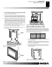
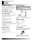
Model VSGF28NVA
Blower Kit Model GA3750 Series
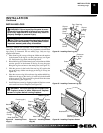
This optional non-thermostat blower kit features a variable con-
trol which allows you to select the speed you desire. After about 15
minutes, turn the blower on to deliver heated air at the top louvers.
Follow the installation instructions on pages 8 and 9 of this manual.
IMPORTANT:
Light your gas appliance with the blower off.
Note:
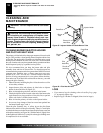
Periodically check the louvers of the firebox and remove
any dust, dirt, or other obstructions.
Blower Kit Model GA3650T Series
Locate the blower switch by opening the lower louver on fire-
place. Blower switch is located at lower left inside louver door.
The GA3650T thermostat-controlled blower has a variable speed
control with an ON/OFF switch. The blower will start when the
thermostat senses a sufficient increase in firebox temperature.
IMPORTANT:
Light your gas appliance with the blower off.
BLOWER OPERATION
WARNING: This fireplace has a three-prong,
grounded electrical plug. This plug helps protect you
against electrical shock. Only connect plug to a
properly grounded, three-prong receptacle. Do not
cut or remove the grounding prong from this plug.
Model VSGF28NTC
WARNING: Do not operate heater between locked
positions.
CAUTION: Do not try to adjust heating levels by
using the equipment shutoff valve.
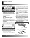
VARIABLE CONTROL
OPERATION
The variable control valve can be set to any heat setting and flame
height desired, by simply turning the control knob until that setting
is attained. Even the lowest setting provides realistic flames and
glowing embers from two burners. Selecting higher settings pro-
duces greater heat output. This results in increased heating comfort.
Shutting Off Fireplace
1. Turn control knob clockwise
Clockwise
to the HIGH position.
2. Slightly depress control knob and turn clockwise
Clockwise
to the PILOT position.
3. Slightly depress control knob and turn clockwise
Clockwise
to the OFF position.
OPERATING FIREPLACE
Continued
MANUAL LIGHTING
PROCEDURE
1. Follow steps 1 through 5 under Lighting Instructions, page 15.
2. Depress control knob and light pilot with match.
3. Keep control knob pressed in for 30 seconds after lighting
pilot. After 30 seconds, release control knob. Now follow
step 8, column 1.
TO TURN OFF GAS
TO APPLIANCE
OPERATING FIREPLACE (MANUALLY CONTROLLED MODELS)
Lighting Instructions (Cont.)
Variable Control Operation
To Turn Off Gas To Appliance
Manual Lighting Procedure
Blower Operation
7. Keep control knob pressed in for 30 seconds after lighting
pilot. After 30 seconds, release control knob.
Note:
If pilot goes out, repeat steps 3 through 7.
• If control knob does not pop out when released, contact
a qualified service person or gas supplier for repairs.
8. Slightly depress and turn control knob counterclockwise
C-clockwise
to the HIGH position. Both burners should light.
Set control knob to either HIGH or LOW.
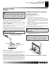
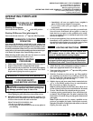
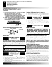
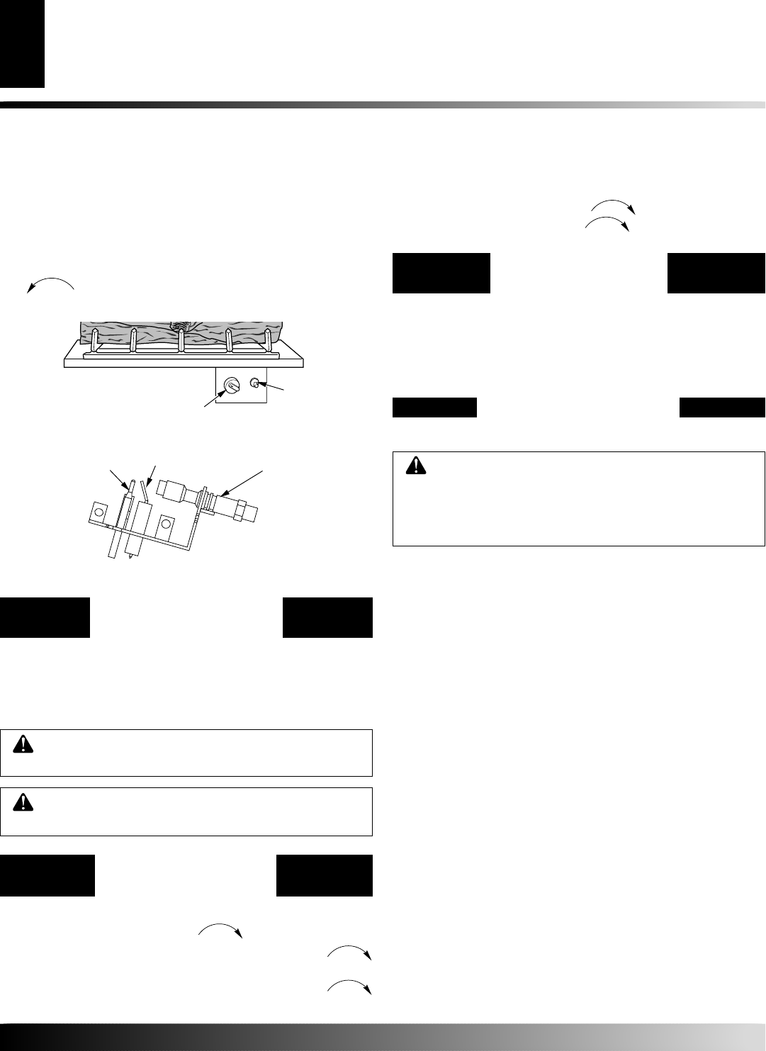
Figure 30 - Pilot
IGNITOR
Figure 29 - Control Knob and Ignitor Button Location
Ignitor Button
Control Knob
Thermocouple
Ignitor Electrode
Pilot Burner
Shutting Off Burners Only (pilot stays lit)
1. Turn control knob clockwise
Clockwise
to the HIGH position.
2. Press in and turn clockwise
Clockwise
to the PILOT position.