


Special offers from our partners!

Find Replacement BBQ Parts for 20,308 Models. Repair your BBQ today.
107157-01F
22
For more information, visit www.desatech.com
For more information, visit www.desatech.com
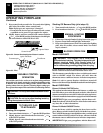
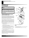
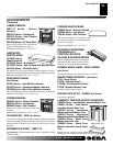
EQUIPMENT SHUTOFF VALVE - GA5010
For all models. Equipment shutoff valve with 1/8" NPT tap. Fits 1/2"
NPT pipe.
ACCESSORIES
Purchase these fireplace accessories from your local dealer. If they
can not supply these accessories, call DESA International’s Sales
Department at 1-866-672-6040 for information. You can also write
to the address listed on the back page of this manual.
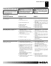
SERVICE HINTS
When Gas Pressure Is Too Low
• pilot will not stay lit
• burners will have delayed ignition
• fireplace will not produce specified heat
You may feel your gas pressure is too low. If so, contact your local
natural gas supplier.
TECHNICAL SERVICE
You may have further questions about installation, operation, or
troubleshooting. If so, contact DESA International’s Technical
Service Department at 1-866-672-6040. When calling please have
your model and serial numbers of your heater ready.
You can also visit DESA International’s technical services web site
at www.desatech.com.
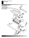
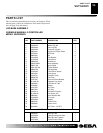
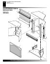
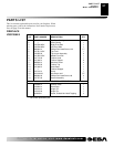
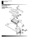
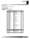
REPLACEMENT PARTS
Note:
Use only original replacement parts. This will protect your
warranty coverage for parts replaced under warranty.
PARTS UNDER WARRANTY
Contact authorized dealers of this product. If they can’t supply
original replacement part(s), call DESA International’s Technical
Service Department at 1-866-672-6040.
When calling DESA International, have ready
• your name
• your address
• model and serial numbers of your fireplace
• how fireplace was malfunctioning
• type of gas used (propane/LP or natural gas)
• purchase date
Usually, we will ask you to return the part to the factory.
PARTS NOT UNDER WARRANTY
Contact authorized dealers of this product. If they can’t supply original
replacement part(s), call DESA International at 1-866-672-6040 for
referral information.
When calling DESA International, have ready
• model number of your fireplace
• the replacement part number
SPECIFICATIONS
Btu (Low/High) 20,000/28,000
Type Gas Natural Gas Only
Ignition Piezo
Manifold Pressure 3.4" W.C.
Inlet Gas Pressure (in. of water)
Maximum 10.5"
Minimum 5"
Shipping Weight 100 lbs. T-stat Model
97 lbs. Manual Model
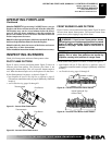
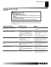
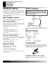
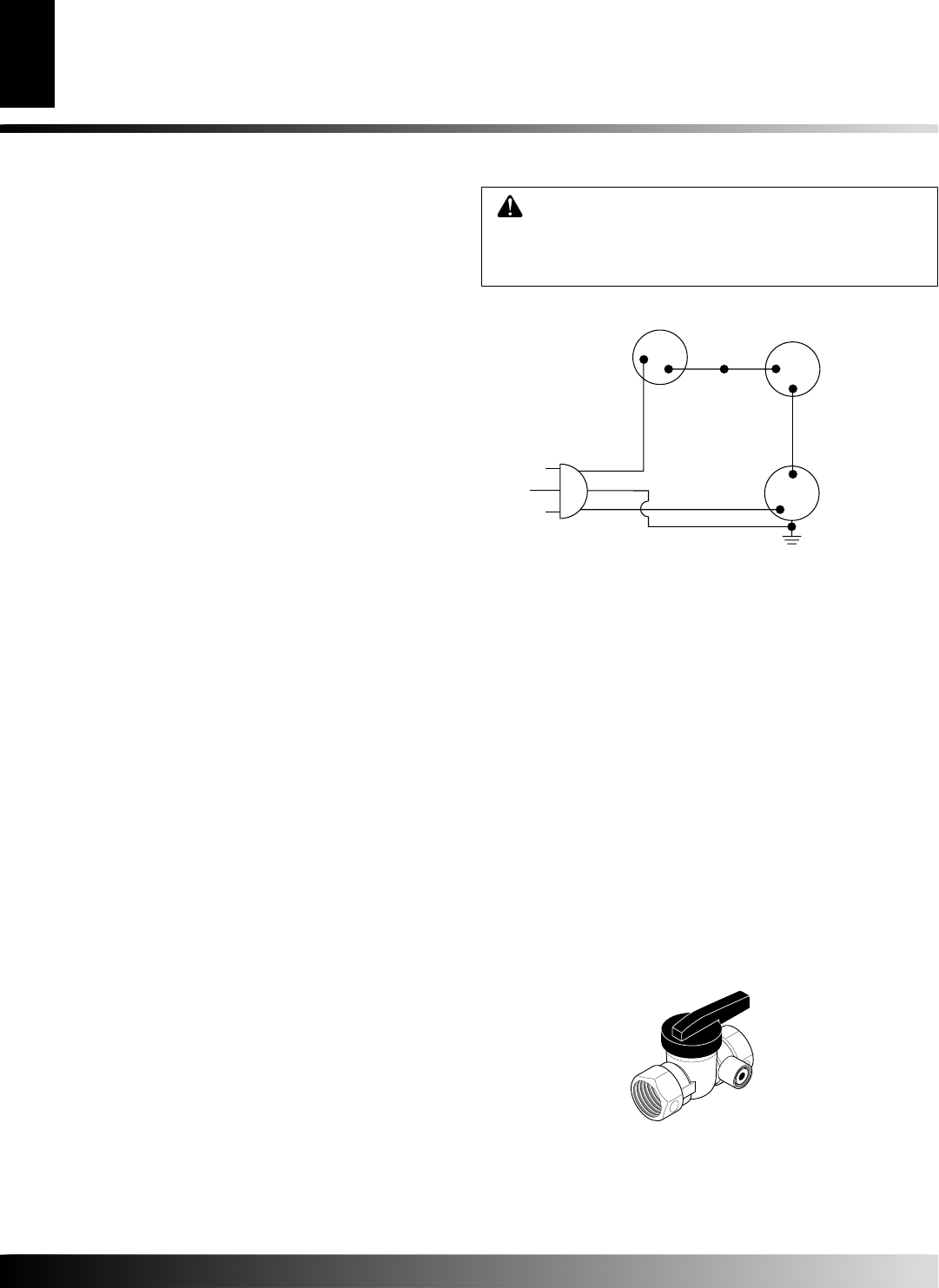
WIRING DIAGRAM
Red
Variable
Fan Switch
Fan Switch
(N.O.)
Green
White
On
110/115
V.A.C.
Blower
Motor
Black
Off
1
2
Black
Blue
CAUTION: Label all wires prior to disconnection
when servicing controls. Wiring errors can cause
improper and dangerous operation. Verify proper
operation after servicing.
Figure 37 - Blower Wiring Diagram for Thermostat-Controlled
Models
TECHNICAL SERVICEWIRING DIAGRAM
REPLACEMENT PARTS
SERVICE HINTS
WIRING DIAGRAM
SPECIFICATIONS
ACCESSORIES