


Special offers from our partners!

Find Replacement BBQ Parts for 20,308 Models. Repair your BBQ today.
www.desatech.com
108795-01N12
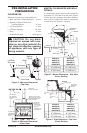
OPTIONAL WIRELESS HAND-HELD
REMOTE CONTROL INSTALLATION
Note: If using optional wireless hand-held remote
control, the wall switch is no longer operational.
Installing Receiver
1. Remove the front refractory access panel by
lifting up and angling out of the firebox opening
(see Figure 13, page 11) to expose controls.
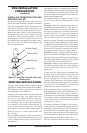
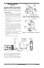
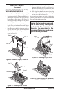
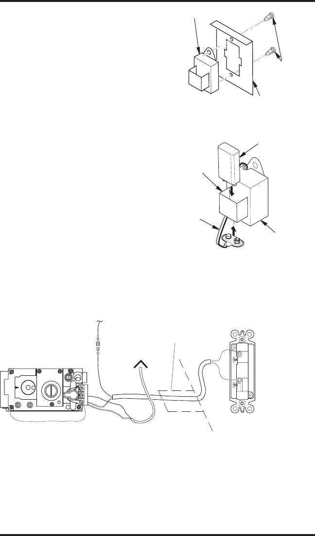
2. Disconnect wall switch wires from TH
and TH/TP terminals on control valve (see
Figure 14).
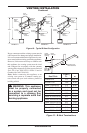
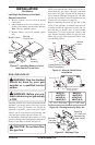
3. Install remote receiver unit onto mounting
bracket using the two plastic mounting clips
(see Figure 15).
4. Connect wires to control circuit. Connect
white wire to terminal marked TH/TP on
control valve. Connect red wire to male blade
connector provided at open end of safety cir
-
cuit wiring (see Wiring Diagram, page 22).
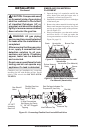
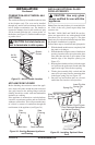
5. Locate the battery clip mounted on the back
of the receiver (see Figure 16).
6. Slide 9-volt battery (not included) through the
clip. Note: Only use alkaline battery.
7. Attach the terminal wires to the battery (see
Figure 16).
8. Replace refractory brick access panel.
Note: If any of the original wire as supplied must
be replaced, use 18 AWG TYPE CL2 (UL) 105 C
(25 ft. length MAXIMUM) or equivalent.
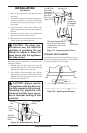
Conduit Sleeve
To Safety Circuit
Route Millivolt
Through Gas Line
To Thermopile
Wires (Supplied)
Wall Switch
(Supplied)
(Back View)
IN
TH
TP
THTP
IN
OUT
O
F
F
P
I
L
O
T
O
N
INSTALLATION
Continued
Figure 14 - Wall Switch Wiring Diagram
Figure 15 - Installing Remote Receiver
(Shown from Rear of Mounting Bracket)
Receiver
Mounting Bracket
Plastic
Mounting
Clips
Figure 16 - Installing Battery in Receiver
Battery
Clip
9-Volt Battery
Receiver
Terminal
Wires