


Special offers from our partners!

Find Replacement BBQ Parts for 20,308 Models. Repair your BBQ today.

www.desatech.com
108795-01N 11
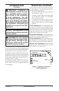
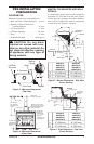
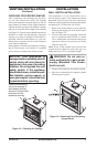
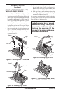
CHECKING FOR PROPER VENTING
After completing and checking the electrical,
gas and vent connections, follow the lighting
instructions and allow the main burner to run for
approximately 5 minutes. Hold a lighted match or
cigarette near the top edge of the fireplace opening
and play it along the entire length of the opening
(see Figure 12). Proper venting should tend to draw
the flame or smoke into the appliance. Improper
venting or escaping of spillage of burned gas, is
indicated when the match flickers or goes out.
Smoke from a cigarette will also tend to disperse
away from the appliance.
If the appliance is found to be improperly venting,
shut it off and notify your installer or a qualified
service agency to inspect the venting system.
NOTICE: This appliance is
equipped with a vent safety shutoff
switch which will shut down the
appliance in the case of a venting
problem. Do not bypass the vent
safety switch. If the appliance
should shut down, contact a quali-
fied installer, service agency or
your gas supplier to have the vent
inspected before operating.
VENTING INSTALLATION
Continued
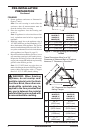
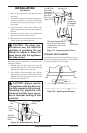
Check this area along
the entire top edge of
the fireplace opening.
Smoke or flame should
be drawn into the
appliance opening.
Figure 12 - Checking for Spillage
INSTALLATION
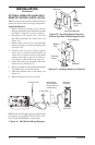
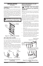
WALL SWITCH INSTALLATION
The installation of a wall switch allows you to
activate the gas control valve without the normal
household electricity since the valve operates on
millivolt current supplied by the heat generated by
the thermopile. To install the wall switch:
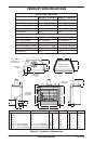
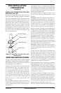
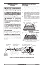
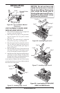
1. Remove the front refractory access panel by
lifting up and angling out of the firebox open
-
ing (see Figure 13).
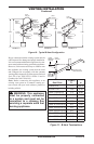
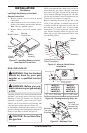
2. Use wire and connectors provided. Attach red
wire to terminal marked TH/TP on control
valve. Attach white wire to blade connector on
open end of safety circuit wiring (see
Wiring
Diagram, page 22).
Note: If any of the original wire from the unit
control must be replaced, use the same type or a
higher rated wire (25 ft. maximum length).
WARNING: Do not wire re-
mote wall switch to main power
supply (Standard 120v house-
hold current).
3. Locate wall switch in a convenient location.
4. After wire connections are complete, replace
refractory access panel.
Figure 13 - Removing Front Refractory
Access Panel