


Special offers from our partners!

Find Replacement BBQ Parts for 20,308 Models. Repair your BBQ today.
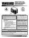
105706-01B
For more information, visit www.desatech.com
For more information, visit www.desatech.com
7
7
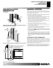
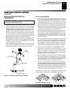
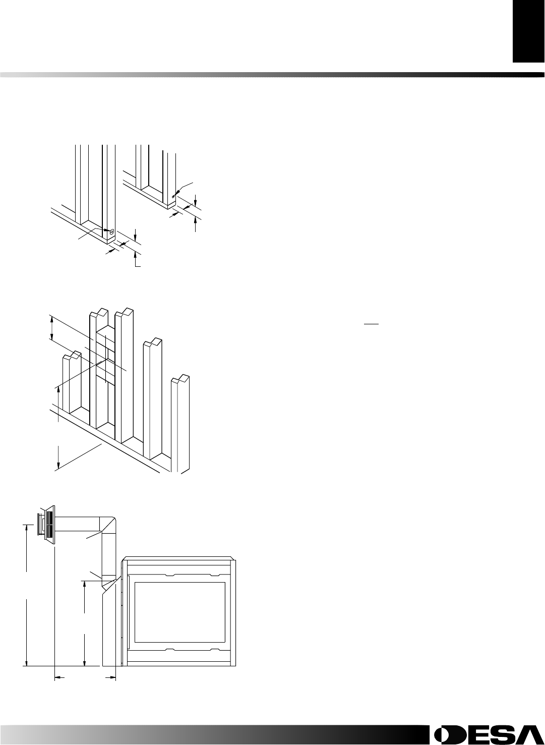
3" (7.6cm)
1" (2.5cm)
Dia. Hole
3"
(7.6cm)
2" (5.1cm)
Dia. Hole
1"
(2.5cm
)
2"
(5.1cm
)
Height
Depends On
Installation
10"
(25.4cm)
Square Min.
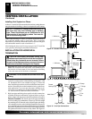
Figure 10 - Hole Locations For Gas Line and Electric Wires for
Peninsula and See-Thru Fireplaces
Figure 11 - Rough Opening for Installing Exterior Vent Terminal
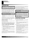
GENERAL VENTING
These models are approved for use with Simpson Dura-Vent 6
5
/8"
direct-vent pipe components and terminations as well as both flex and
rigid Vanguard vent components.
Your fireplace is approved to be vented either through the side wall,
or vertically using the following guidelines:
• Only use Vanguard or Simpson Dura-Vent GS venting compo-
nents or kits specifically approved for this fireplace.
• Minimum clearance between vent pipes and combustible mate-
rials is 1" (2.5cm), except where stated otherwise.
• Combustible material may be flush with the top front of fire-
place with a maximum thickness of 3/4".
• Do not recess venting terminals into a wall or siding.
• Install horizontal venting with a 1/4" rise for every 12" of
run toward the termination.
• You may paint the vent terminal with 450°F (232°C) heat-resis-
tant paint to coordinate with the exterior finish.
• There must not be any obstruction such as bushes, garden sheds,
fences, decks, or utility buildings within 24" from the front of
the termination cap.
• Do not locate termination cap where excessive snow or ice build
up may occur. Be sure to clear vent termination area after snow
falls to prevent accidental blockage of venting system. When
using snow blowers, do not direct snow towards vent termina-
tion area.
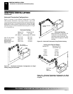
LOCATION OF VENT TERMINATION
When locating vent termination, it is important to observe the
minimum clearances shown in Figure 13, page 8. You will avoid
extra framing by positioning your fireplace against an already
existing framing member. The sides of the fireplace may be posi-
tioned directly against combustible walls.
*Check with local codes or with the current CAN/CGA B149[.1 or
.2] Installation Codes for Canada or the USA Installations follow
the current National Fuel Gas Code, ANSI Z223.1/NFPA 54.
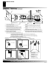
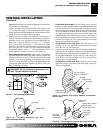
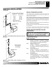
Vertical Height
Depends on
Installation
26
3
/
8
"
(67cm)
Horizontal
Length Depends
on Installation
90
o
Elbow
45
o
Elbow
Refer to Pages 10 through 16
for Horizontal and Vertical
Installation Details
Figure 12 - Vent Opening Height
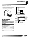
PRE-INSTALLATION
PREPARATION
Continued
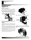
PRE-INSTALLATION PREPARATION
Framing (Cont.)
GENERAL VENTING
Location of Vent Termination