


Special offers from our partners!

Find Replacement BBQ Parts for 20,308 Models. Repair your BBQ today.
105706-01B
For more information, visit www.desatech.com
For more information, visit www.desatech.com
10
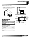
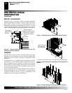
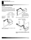
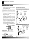
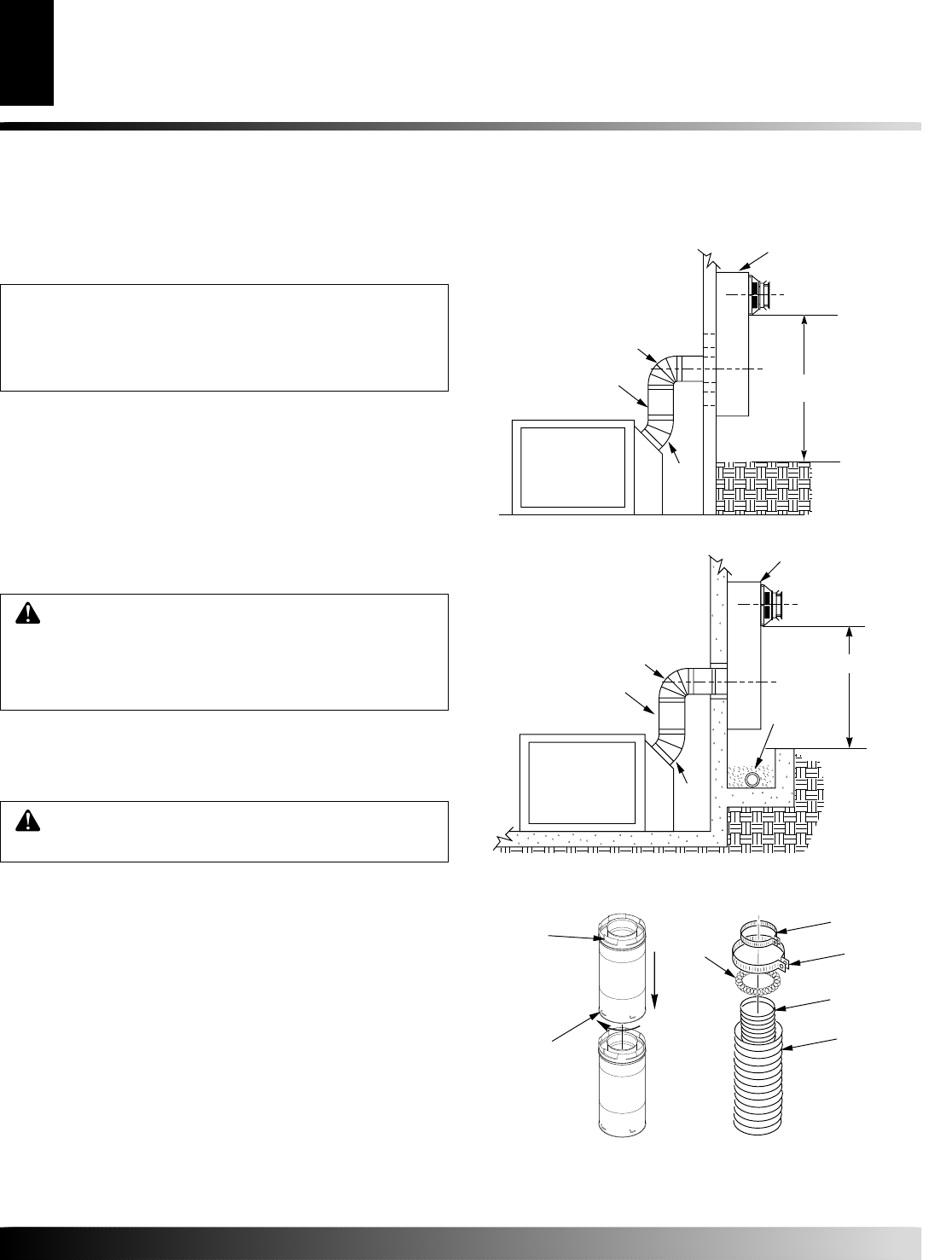
Figure 16 - Vent Pipe Connections
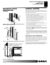
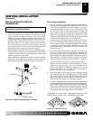
Installing Vent System in a Chase
A chase is a vertical box-like structure built to enclose venting that runs
along the outside of a building. A chase is not required for such venting.
NOTICE: Treatment of firestops and construction of
the chase may vary from building type to building
type. These instructions are not substitutes for the
requirements of local building codes. You must fol-
low all local building codes.
Note:
When installing in a chase, you should insulate the chase as
you would the outside walls of your home. This is especially
important in cold climates. Minimum clearance between vent pipes
and combustible materials such as insulation is 1".
After framing the chase (see Framing on pages 6 and 7) install the
vent system by following the installation instructions.
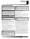
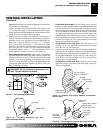
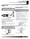
INSTALLATION FOR HORIZONTAL
TERMINATION
CAUTION: Horizontally terminated venting con-
figurations require one foot of vertical rise from the 45°
elbow before any horizontal run can be made. Failure
to meet venting requirements may cause performance
problems and possible damage to the fireplace.
1. Determine the route your horizontal venting will take.
Note:
The location of the horizontal vent termination on
the exterior wall must meet all local and national building
codes and must not be blocked or obstructed.
WARNING: Do not recess vent terminal into a wall
or siding.
Snorkel terminations are available for terminations requiring a
vertical rise on the exterior of the building (see Figures 14 and
15). Snorkel kit SVK is also available (see page 17). Follow the
same installation procedures used for standard horizontal termi-
nations. If installing the snorkel termination below grade (base-
ment applications), you must provide proper drainage to pre-
vent water from entering the snorkel termination (see Figure
15). Do not back fill around the snorkel termination.
2. Rigid vent pipes and fittings have special twist-lock connections.
Assemble the desired combination of pipe and elbows to the ap-
pliance adaptor with pipe seams oriented towards the wall or floor.
Twist-lock Procedure: The female ends of the pipes and fittings
have four locking lugs (indentations). These lugs will slide straight
into matching slots on the male ends of adjacent pipes and fittings.
(All connections must be sealed with high temperature silicone seal-
ant as specified in the second warning statement on page 9.) Push the
pipe sections together and twist one section clockwise approximately
one-quarter turn until the sections are fully locked. See Figure 16.
VENTING INSTALLATION
Continued
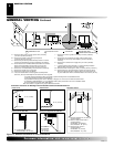
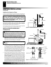
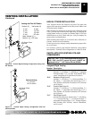
Figure 15 - Snorkel Termination with Drainage Pipe
Figure 14 - Snorkel Termination
Snorkel
1' Minimum
90º
45º
Adequate
Drainage
Snorkel
1' Minimum
90º
45°
Female
Locking Lugs
Male Slots
Rigid Vent Pipe Flexible Vent Pipe
Spacer
Spring
4" Clamp
7" Clamp
4" Flex
Pipe
7" Flex
Pipe
VENTING INSTALLATION
Installation Planning (Cont.)
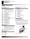
Installation for Horizontal Termination
12" Minimum
12" Minimum