


Special offers from our partners!

Find Replacement BBQ Parts for 20,308 Models. Repair your BBQ today.
105706-01B
For more information, visit www.desatech.com
For more information, visit www.desatech.com
14
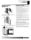
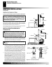
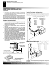
Figure 26 - Cathedral Ceiling Support Box Installation
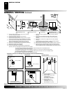
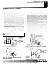
Non-hardening Mastic
under all edges of support
box before nailing
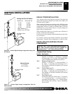
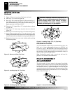
Figure 27 - Installed Cathedral Ceiling Support Box
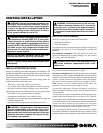
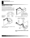
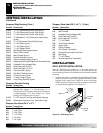
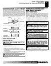
Vertical Termination Configurations
Figures 28 through 31 show four different configurations for vertical
termination. All connections must be sealed with high temperature
silicone sealant as specified in the second warning statement on page 9.
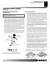
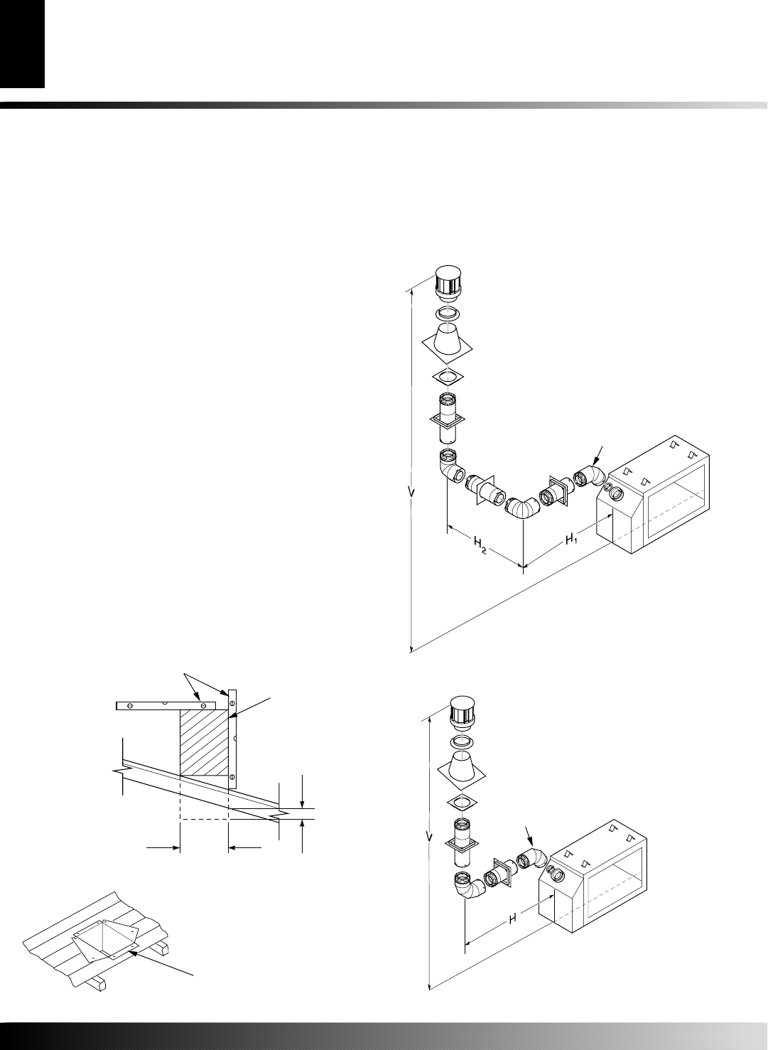
Venting with Two 90° Elbows
Vertical (V) Horizontal (H
1
) +
Horizontal (H
2
)
5' min. 2' max.
6' min. 4' max.
7' min. 6' max.
8' min. 8' max.
20' max. 8' max.
Venting with One 90° Elbow
Vertical (V) Horizontal (H)
5' min. 2' max.
6' min. 4' max.
7' min. 6' max.
8' min. 8' max.
20' max. 8' max.
Cut hole 1/8" larger
than support box when
projected onto roofline
2" minimum below
finished ceiling
Cathedral ceiling
support box
Level
45° Starter Elbow
Required
45° Starter
Elbow
Required
7. Twist-lock the vent cap onto the last section of vent pipe and
seal with high temperature silicone sealant as specified in the
second warning statement on page 9.
Note:
If the vent pipe passes through any occupied areas above the first
floor, including storage spaces and closets, you must enclose pipe. You
may frame and sheetrock the enclosure with standard construction
material. Make sure and meet the minimum allowable clearances to
combustibles. Do not fill any of the required air spaces with insulation.
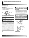
Cathedral Ceiling Installation
1. Remove shingles or other roof covering as necessary to cut the
rectangular hole for the support box. Mark the outline of the
cathedral ceiling support box on the roof sheathing using the
locating hole as a center point.
2. Cut the hole 1/8" larger than the support box outline (see
Figure 26).
3. Lower the support box through the hole in the roof until the
bottom of the box extends at least 2" below the ceiling (see
Figure 26). Align the support box vertically and horizontally
using a level. Temporarily tack the support box in place through
the inside walls and into the roof sheathing.
4. Using tin snips, cut the support box from the top corners down
to the roofline and fold the resulting flaps over the roof sheath-
ing (see Figure 27). Apply a bead of non-hardening mastic around
the top edges of the support box to make a seal between the box
and the roof. Nail in place with roofing nails. Remove any com-
bustible material that might be inside of the support box.
5. Complete the cathedral ceiling installation by following the
same procedures outlined in steps 2 through 7 for Flat Ceil-
ing Installation
.
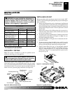
VENTING INSTALLATION
Continued
VENTING INSTALLATION
Installation for Vertical Termination (Cont.)
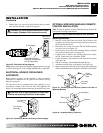
Figure 29 - Vertical Rigid Venting Configuration Using One
90° Elbow
Figure 28 - Vertical Rigid Venting Configuration Using Two 90°
Elbows with Two Horizontal Runs