


Special offers from our partners!

Find Replacement BBQ Parts for 20,308 Models. Repair your BBQ today.
105706-01B
For more information, visit www.desatech.com
For more information, visit www.desatech.com
21
21
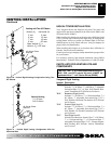
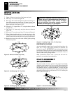
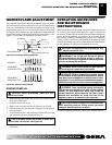
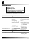
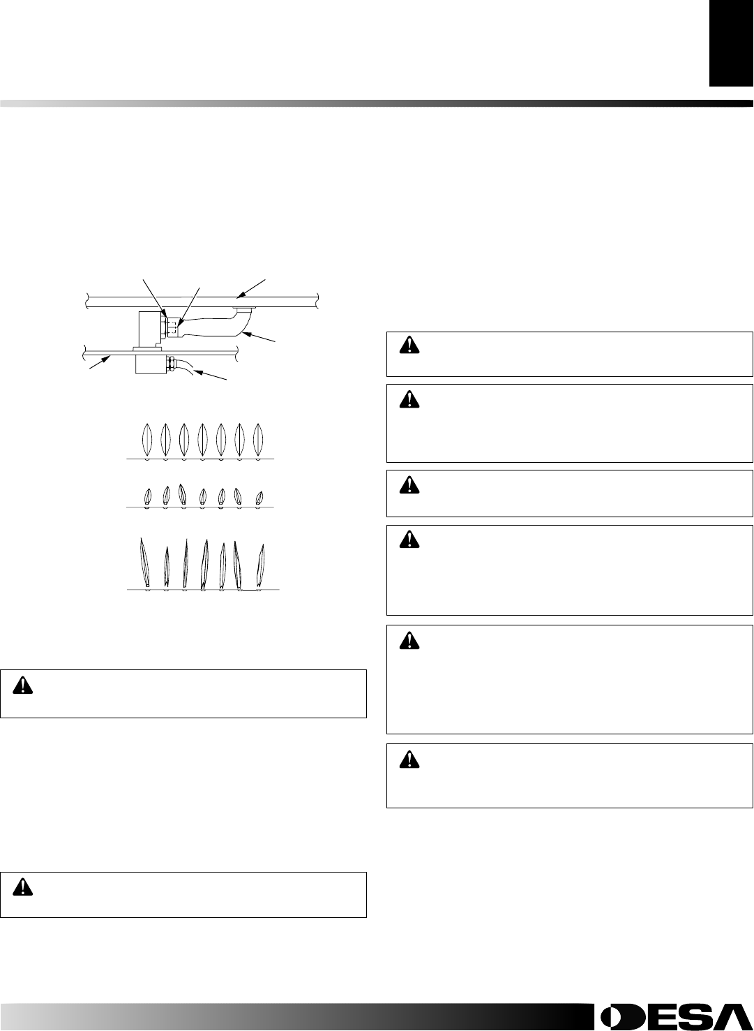
BURNER FLAME ADJUSTMENT
The air shutter, located at the underside of the main burner (see Figure
48), has been factory preset to the proper air-to-gas ratio which results
in an even, clean burning flame across the burner (see Figure 49). If
readjustment is necessary, you can restore the proper air-to-gas ratio
by loosening the air shutter screw and rotating the air shutter until the
proper flame setting is achieved (the shutter's normal setting is “full
opened”. Do not forget to retighten the air shutter screws.
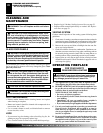
Figure 49 - Burner Flame Patterns
CORRECT
INCORRECT
CLOSE SHUTTER
INCORRECT
OPEN SHUTTER
Short, Sharp, Blowing Flame
Long, Blue Flame with Yellow Tips
Long, Uneven, Yellow Flame
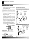
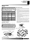
Figure 48 - Connecting Venturi and Orifice
Air Shutter
Orifice
Burner
Firebox Bottom
Venturi Tube
Burner Gas Line
BURNER FLAME ADJUSTMENT
Burner Removal
OPERATING GUIDELINES AND MAINTENANCE INSTRUCTIONS
OPERATING GUIDELINES
AND MAINTENANCE
INSTRUCTIONS
When lit for the first time, the appliance may emit a slight odor for about
16 - 24 hours. This is normal and is due to the “curing” of the logs and
the “burn-in” of internal paints and lubricants used in the manufacturing
process. Keep compartments, logs, burners, and area surrounding the
logs clean by vacuuming or brushing at least twice a year. Temporary
removal of the log set may ease the cleaning of the burner and pilot
assembly. In cleaning, take care not to alter the pilot or burner location.
Be sure appliance is cool before each maintenance session.
CAUTION: The appliance and logs can get very
hot - Handle only when cool.
WARNING: Turn off gas and wall switch before
servicing appliance. Any safety screen or guard re-
moved for servicing the appliance must be replaced
prior to operating the appliance.
WARNING: Make certain wires and gas lines are
not touching the underside of the firebox.
WARNING: Children and adults should be alerted
to the hazards of high surface temperatures, and to
stay away from the appliance to avoid burns or cloth-
ing ignition. Young children should be carefully super-
vised when they are in the same room as the appliance.
WARNING: Have a qualified agency periodically
inspect the vent system at the start of each heating
season, for any obstruction which may hinder its
normal operation. Never obstruct the flow of com-
bustion and ventilation air. Keep the front of the
appliance clear of all obstacles and materials.
CAUTION: Label all wires prior to disconnection
when servicing controls. Wiring errors can cause
improper and dangerous operation.
For further operating guidelines, contact your authorized dealer.
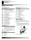
BURNER REMOVAL
CAUTION: Before proceeding, make sure the
entire unit is cool.
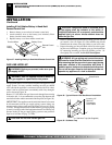
1. Remove the top and bottom louvers and screen. Open the glass
door (left or right side).
2. Carefully remove the log set.
3. Remove the screw that attaches the burner to the bracket.
4. Slide the burner towards the front of the unit, lift, and remove
from the firebox.
5. To reinstall the burner, slide the burner towards the rear of the
unit and secure burner to bracket with screw.
CAUTION: Make certain the orifice is inside the
venturi tube's air shutter, see Figure 48.
6. Replace the log set, close door with latches, and attach screen
and louvers.