


Special offers from our partners!

Find Replacement BBQ Parts for 20,308 Models. Repair your BBQ today.
9
107050
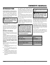
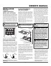
OWNER’S MANUAL
INSTALLATION
Continued
Continued
WARNING: All gas piping
and connections must be tested
for leaks after the installation is
completed.
After ensuring that the gas valve
is on, apply a soap and water
solution to all connections and
joints. If bubbles appear, leaks
can be detected and corrected.
Do not use an open flame for leak
testing and do not operate any
appliance if a leak is detected.
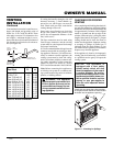
Complete your gas installation by connect-
ing incoming gas line with flexible gas line.
Secure tightly with wrench but Do NOT
Overtighten.
CAUTION: Compounds used
on threaded joints of gas piping
shall be resistant to the action of
Liquefied Petroleum (LP or pro-
pane), and should be applied
lightly to ensure excess sealant
does not enter the gas line.
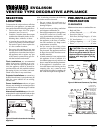
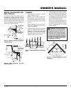
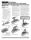
GAS LINE HOOK-UP
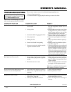
Figure 14 - Equipment Shutoff Valve
Installation
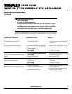
Figure 15 - Routing Incoming Gas Line
WARNING: Gas line hookup
should be done by your gas sup-
plier or a qualified service person.
WARNING: Before you pro-
ceed, make sure your gas supply
is OFF.
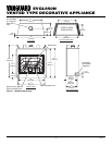
11"
(279mm)
4
5
/
8
"
(117mm)
5
5
/
8
"
(143mm)
1/2" NPT Incoming
Black Iron Gas
Line
Flexible Gas Line (1 Provided) Can Be
Extended Out from 3 Sides
Typical Exterior Wall Gas
Shutoff Installation
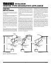
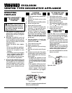
CAUTION: Do not kink flex-
ible gas line.
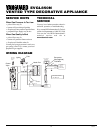
DESA recommends that a black iron gas
line be routed from the gas source, through
a sediment trap (shown in Figure 16), and
into the appliance, Once connected through
the appliance, a flexible gas line may be
used for ease of installation to gas control
valve (see Figure 17).
Before connecting the black iron gas line to the
inside of the appliance a sediment trap must be
included outside the appliance between the
gas line and the equipment shutoff valve. It
must extend down three (3) inches beyond the
center of the pipe. Prepare incoming black
iron gas line with teflon tape or pipe joint
compound (Check with local building codes).
An equipment shutoff valve has been in-
cluded in the appliance’s gas supply system.
You may consider installing an extra gas
shutoff valve outside the appliance’s enclo-
sure (check with local codes) where it can be
accessed more conveniently with a key
through a wall as shown in Figure 14.
In conformance with local codes, route a 1/2”
NPT gas line towards the appliance coming
in from any of the 3 directions shown in
Figure 15.
Key
Extension
Equipment
Shutoff Valve
3" Min.
(76mm)
Side Wall
Of Appliance
Incoming 1/2" Gas Line
Permitted by Local Codes
Sediment Trap
(Not Supplied)
Figure 16 - Sediment Trap
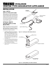
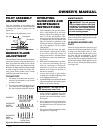
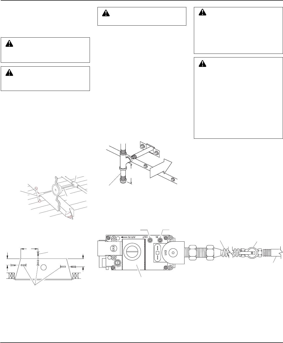
Equipment
Shutoff
Valve
Flexible Gas Line
Do NOT Kink
1/2" NPT
Incoming
Gas Line
Inlet
Pressure
Tap
Outlet
Pressure
Tap
Note:
1) Wire Connections
Not Shown for Clarity
2) * 1/8" NPT Plugged
Tapping
Figure 17 - Connecting Flexible Gas Line to Electronic Valve
Red Surface Indicates
For Propane/LP Use Only