


Special offers from our partners!

Find Replacement BBQ Parts for 20,308 Models. Repair your BBQ today.
5
107050
OWNER’S MANUAL
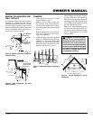
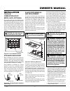
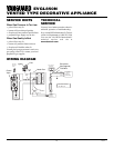
MANTEL CLEARANCES AND
WALL DETAILS
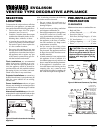
A combustible mantel shelf maybe installed a
maximum 9" (229mm) from the wall and
must have a minimum distance of 18" (457mm)
above the fireplace opening. Figures 5 and 6
show the minimum allowable distances from
various combustible mantle components in
relation to the fireplace opening.
Figure 5 - Mantel Clearances - Side View
(Cross Section)
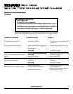
Figure 6 - Side Clearances - Top View
(Cross Section)
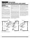
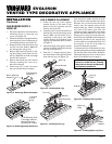
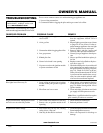
FRAMING
1. Frame appliance enclosure as illus-
trated in Figures 7 and 8.
Note:
If a wall covering is used to line
the enclosure, then all measurements
must be from the surface of the covering.
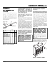
2. Place the appliance into the framing and
secure it.
Note:
If appliance is to be raised above
floor level, a platform must be built to
support the appliance.
3. Install the supply line to the appliance
using a 1/2" NPT black iron gas line ter-
minating 2
5
/16" above the bottom of the
appliance. The gas line may be installed
from either side or from the rear of the
appliance (see Figure 15, page 9).
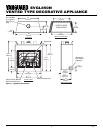
Figure 7 - Rough Opening for Installing in
Wall
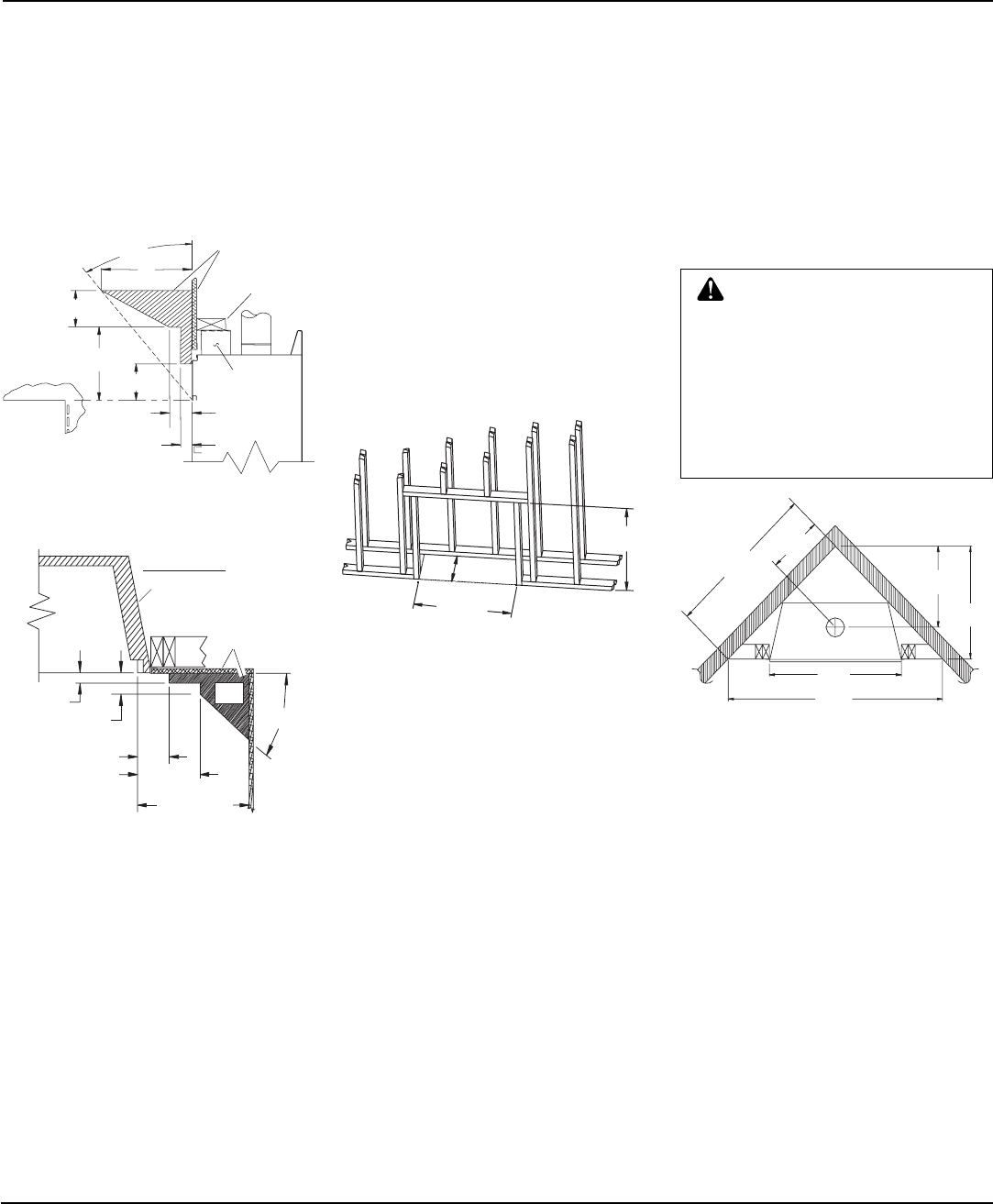
Figure 8 - Rough Opening for Corner
Installation
41
7
/
8
"
(1061mm)
15"
(381mm)
36
1
/
4
"
(921mm)
59
1
/
4
"
(1505mm)
29
5
/
8
"
(752mm)
21
3
/
16
"
(538mm)
CORNER INSTALLATION
15
5
/
8
" Min.
(397mm)
36
1
/
4
"
(921mm) Min.
38
1
/
8
"
(968mm) Min.
29.5°
9"
(229mm)
6"
(152mm)
12"
(305mm)
6" Min.
(152mm)
3" (76mm)
1
1
/
2
"
(38mm) Max.
1
1
/
2
"
(38mm) Max.
3" (76mm) Max.
6" (152mm) Min.
Within 12"
(305mm)
18" (457mm)
Min.
33°
TOP VIEW
Safe
Zone
Combustible
Materials
Spacer
Header
Combustible
Material May
Be Used
WARNING: When finishing ap-
pliance, Do not overlap combus-
tible material onto the black front
face. Brick, tile, or other noncom-
bustible materials may be applied
to the face provided that any gap
is between the material used and
the face is caulked with a non-
combustible caulking.
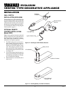
4. Feed flexible gas line through one of three
gas line conduit sleeve and repack insu-
lation to cover any openings. Prepare the
incoming gas line with teflon tape or pipe
joint compound and hook-up incoming
gas line to the flexible gas line.
Note:
If 1/2" NPT black iron pipe does
not mate with fitting at the end of flex-
ible gas line, remove fitting and replace
with a 37 degree flare 3/4"-12, 1/2" NPT
(female) fitting.
Outer Surround