


Special offers from our partners!

Find Replacement BBQ Parts for 20,308 Models. Repair your BBQ today.
25
106424
OWNER’S MANUAL
O
F
F
P
I
L
O
T
O
N
L
O
I
H
ON
OFF
REMOTE
ON
OFF
OPERATING
FIREPLACE
Continued
OPERATING
OPTIONAL BLOWER
ACCESSORY
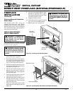
Locate the blower controls by opening
the lower louver panel on the fireplace.
Blower controls are located on the left
side of the switch bracket to the left just
inside the louver panel.
Both the GA3700 manual blower and the
DA3610TA thermostatically-controlled
blower have an ON setting and an OFF
setting. The blower will only run when the
switch is in the ON position. In the OFF
position, the blower will not operate.
Note for DA3610TA Only:
If you are
using DA3610TA blower, your fireplace
and blower will not turn on and off at the
same time. The fireplace may run for
several minutes before the blower turns
on. After the heater modulates to the pilot
position, the blower will continue to run.
The blower will shut off after the firebox
temperature decreases.
The blower helps distribute heated air
from the fireplace. Periodically check the
louvers of the firebox and remove any
dust, dirt, or other obstructions that will
hinder the flow of air.
INSPECTING
BURNERS
Check pilot flame pattern and burner flame
patterns often.
PILOT ASSEMBLY
The pilot assembly is factory preset for the
proper flame height. Alterations may have
occurred during shipping and handling. Call
a qualified service person to readjust the
pilot if necessary.
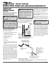
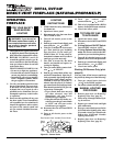
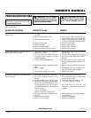
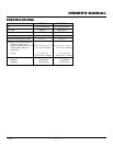
The height of the thermopile must be 3/8" to
1/2" above the pilot flame as shown in Figure
53. The thermocouple must be at a height of
about 1/8" above the pilot flame. The flame
from the pilot burner must extend beyond
both the thermocouple and thermopile.
If your pilot assembly does not meet these
requirements:
• turn fireplace off (see To Turn Off Gas to
Appliance, page 24)
• see Troubleshooting, pages 27 through 29
Figure 53 - Pilot Assembly
Thermocouple
Thermopile
3/8" to 1/2"
1/8"
Pilot Burner
Piezo
Ignitor
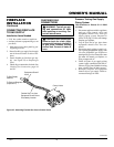
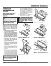
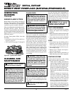
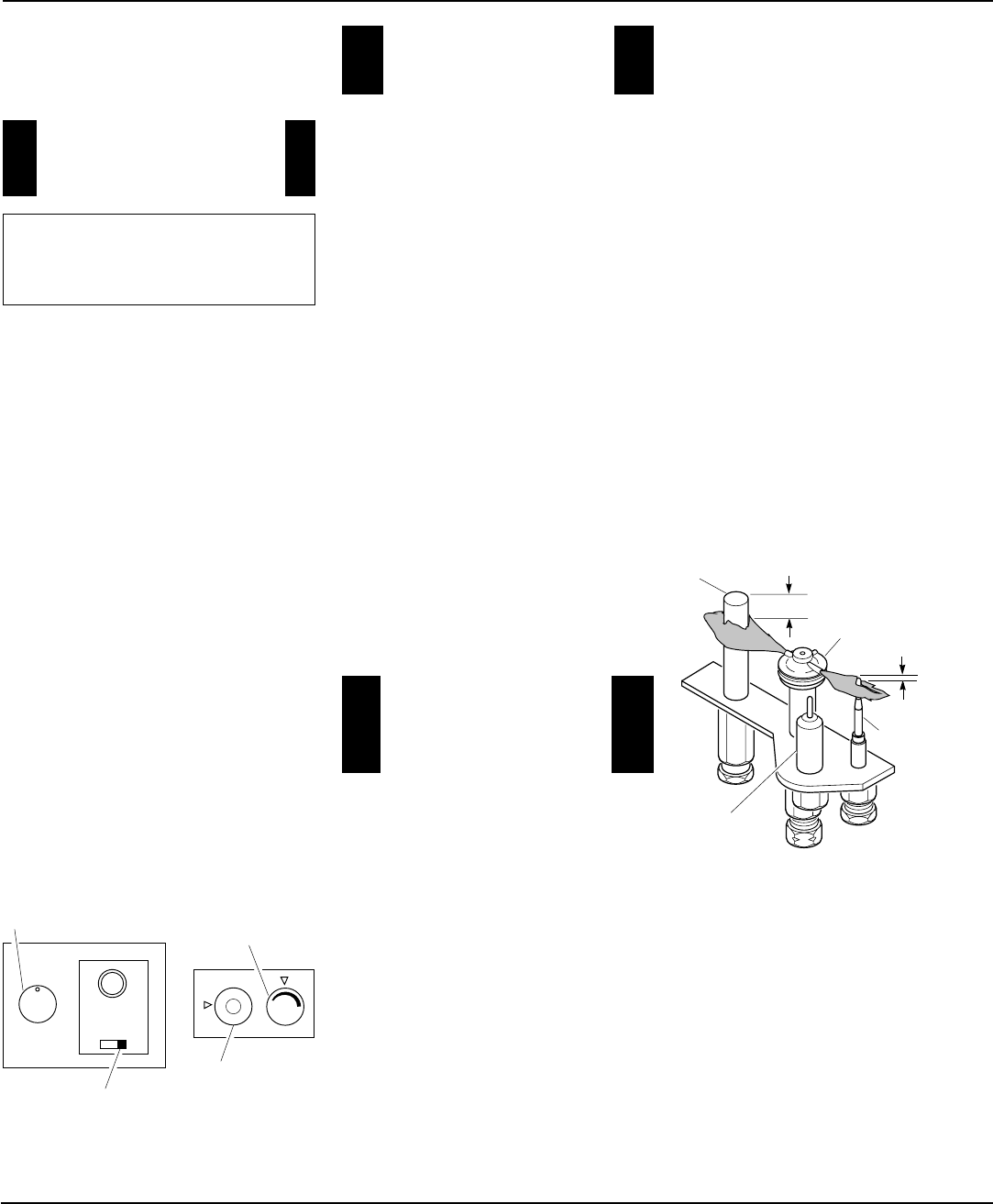
Figure 52 - Setting the Selector Switch,
Gas Control Knob, and Variable Control
Knob for Remote Operation
Selector Switch in
Remote Position
Gas Control
Knob in On
Position
Variable
Control Knob
Blower Control Knob
(Optional Accessory)
OPERATING
OPTIONAL HAND-
HELD REMOTE
1. After lighting, let pilot flame burn for
about one minute. Turn gas control
knob on the control valve to ON posi-
tion. Turn variable control knob any-
where between HI and LO. Slide the
selector switch to the REMOTE po-
sition.
Note:
The burners may light if
hand-held remote ON button was on
when selector switch was last turned
off. You can now turn the burners on
and off with the hand-held remote con-
trol unit.
IMPORTANT:
Do not leave the se-
lector switch in the REMOTE posi-
tion when the pilot is not lit. This will
drain the battery.
IMPORTANT:
Be sure to press the
ON/OFF buttons on the hand-held
remote control unit for up to 3 sec-
onds to assure proper operation.
2. Press the ON/OFF button to turn the
burners on and off. When turning
burners off, the pilot will remain lit.
IMPORTANT:
To turn the pilot off,
manually turn the gas control knob
on the heater to the OFF position.
NOTICE: You must light the pilot
before using the hand-held re-
mote control unit. See
Lighting
Instructions
, page 24.
OPERATING
OPTIONAL GWMS2
WALL MOUNTED
SWITCH
Make sure the heater switch is on AUTO.
This wall switch works just like the con-
ventional light switch. Flip the switch up
for on and down for off.
Note:
Make sure that this switch is not in
a position to be mistaken for a light switch.
This may result in the heater being inad-
vertently turned on without the proper
precautions being taken. See installation
instructions on page 21 of this manual.
Continued