


Special offers from our partners!

Find Replacement BBQ Parts for 20,308 Models. Repair your BBQ today.
21
106424
OWNER’S MANUAL
FIREPLACE
INSTALLATION
Continued
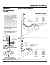
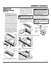
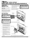
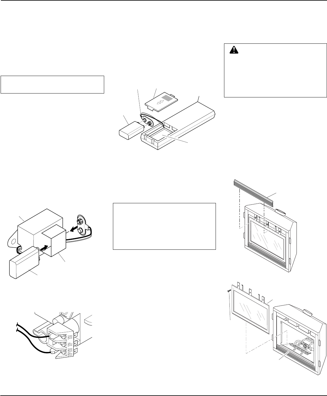
Figure 39 - Attaching Alkaline Battery to
Receiver
9-Volt Alkaline
Battery
Receiver
Terminal
Wires
Battery Clip
1. Open bottom louver and locate the
switch bracket on the left.
2. Unscrew the switch bracket. Lean
bracket forward so you are able to ac-
cess the back of the remote receiver.
3. Locate the battery clip mounted on the
back of the receiver. Slide a 9-volt al-
kaline battery (not included) through
the clip (see Figure 39).
4. Attach the terminal wires to the battery.
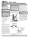
5. Connect wire leads to TH and THTP to
control valve (see Figure 40).
6. Replace the switch bracket.
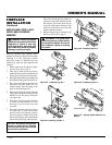
Figure 40 - Connecting Remote Accessories
to Control Valve
To Remote
Accessory
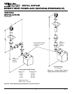
Installing 9-Volt Alkaline Battery in
Hand-Held Remote Control Unit
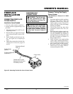
1. Remove battery cover on back of re-
mote control unit.
2. Attach terminal wires to a 9-volt alka-
line battery (not included). Place bat-
tery into the battery housing.
3. Replace battery cover onto remote con-
trol unit.
Figure 41 - Installing Alkaline Battery in
Hand-Held Remote Control Unit
Battery
Cover
9-Volt
Alkaline
Battery
Terminal
Wires
Remote
Control Unit
Battery
Housing
NOTICE: Use only alkaline bat-
teries (not included).
Installing 9-Volt Alkaline Battery
into Receiver
INSTALLING OPTIONAL
WIRELESS HAND-HELD
REMOTE CONTROL - GHRC
SERIES
INSTALLING OPTIONAL
WALL MOUNT SWITCH
GWMS2
NOTICE: The GWMS2 includes
25' of wire for installation. Your
fireplace includes 15' of wire for
accessory installation. Choose the
length that best fits your needs
when installing this accessory.
1. Connect one terminal of the provided
wire for the wall switch to the TPTH
terminal on the valve. Connect remain-
ing wire terminal to the TH terminal
on the valve. Make sure that the wire
terminals are in the positions on the unit
as pictured in Figure 40. If wires are
not connected as shown the switch will
not work.
2. Route the wire through openings pro-
vided on the sides of the fireplace to a
convenient location to mount your switch.
3. Connect one bare wire end to each of the
terminals of the GWMS2 wall switch.
4. Install the wall switch and cover in the
wall.
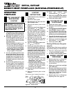
REMOVING/REPLACING
GLASS DOOR
You must remove glass door to install optional
brick liners, logs, lava rock, and ember material.
CAUTION: Do not operate this
fireplace with a broken glass door
panel. Do not operate this fire-
place without the glass door panel
securely in place. For replace-
ment part information see
Re-
placement Parts
, page 30.
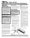
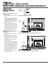
1. Remove the upper louver panel by lift-
ing upward and out (see Figure 42).
2. Remove the screws from the three tabs at
the top of the glass door while holding door
securely keeping it from falling forward.
3. Grasp door by both sides and ease it
upward off of the lower bracket (see
Figure 43).
4. To replace glass door, follow the above
instructions in reverse.
Continued
Figure 43 - Removing/Replacing Glass Door
Figure 42 - Removing Top Louver Panel
Top Louver
Panel
Glass Door
Assembly
Screw
Lower Bracket
for Glass Door
Assembly