


Special offers from our partners!

Find Replacement BBQ Parts for 20,308 Models. Repair your BBQ today.
105443-01E
For more information, visit www.desatech.com
For more information, visit www.desatech.com
15
15
Front
Bac
k
Front
Back
INSTALLATION
Continued
INSTALLATION
Installing Logs
Optional Wireless Hand-Held Remote Control Accessories
WARNING: Failure to position the parts in accor-
dance with these diagrams or failure to use only parts
specifically approved with this heater may result in
property damage or personal injury.
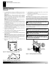
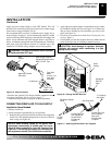
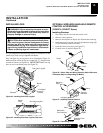
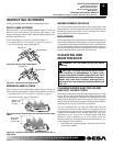
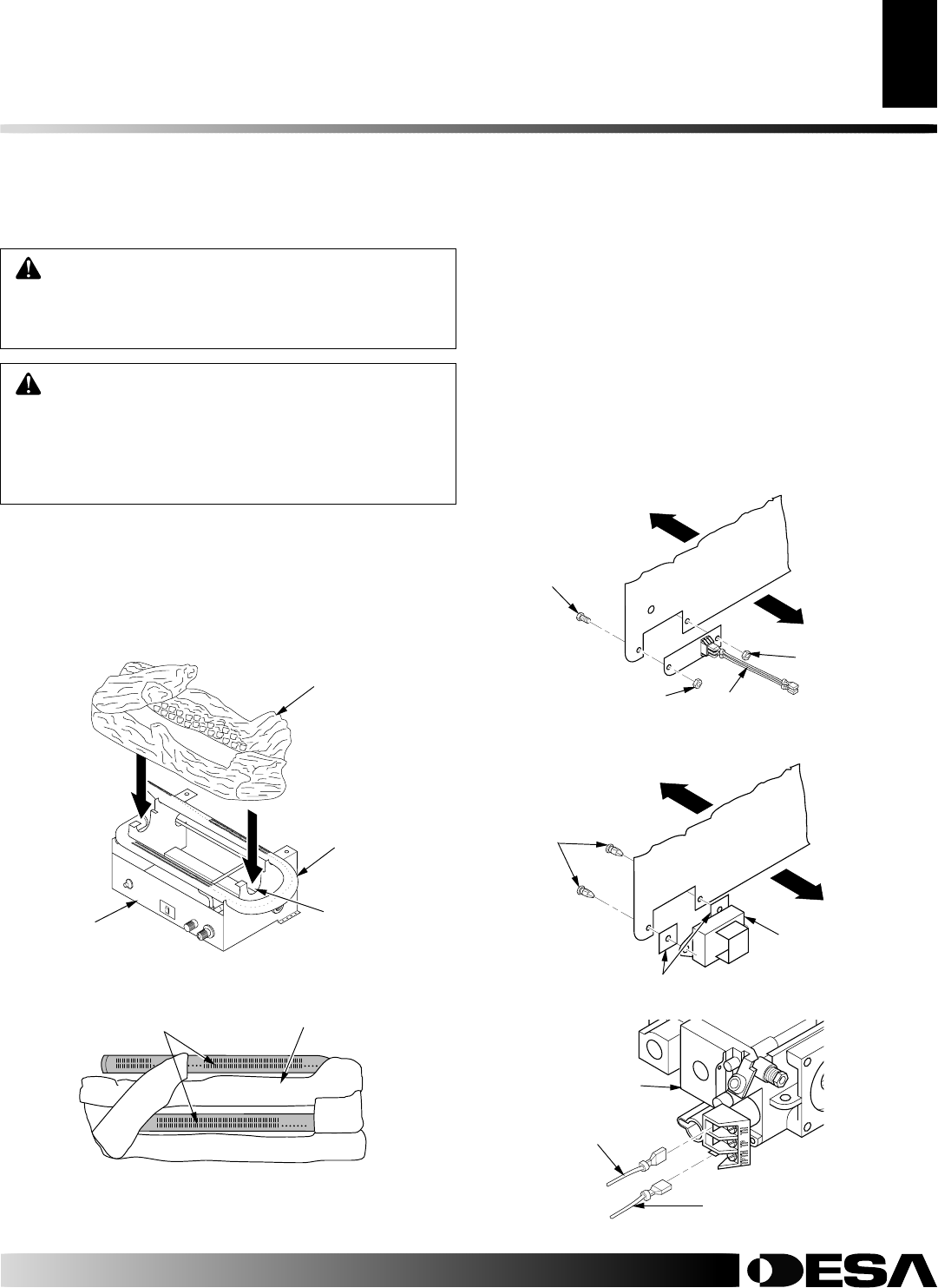
INSTALLING LOGS
It is very important to install the logs exactly as instructed. Do not
modify logs. Only use logs supplied with heater.
Place one-piece log set on grate to fit as illustrated in Figure 24.
Make sure back section of log set is seated into “U”-shaped cutout
in center of chassis (see Figure 24).
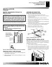
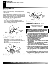
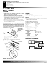
IMPORTANT:
Make sure log
does not cover any burner ports (see Figure 25).
CAUTION: After installation and periodically there-
after, check to ensure that no flame comes in contact
with any log. With the heater set to HI, check to see if
flames contact any log. If so, reposition logs accord-
ing to the log installation instructions in this manual.
Flames contacting logs will create soot.
Figure 24 - Installing One-Piece Log Set
A
U
T
O
O
F
F
O
N
One Piece Log Set
Burner
"U"-shaped
Cutout in
Chassis
Chassis
Figure 25 - Installing One-Piece Log set (Top View)
One Piece Log Set
Burner
Ports
OPTIONAL WIRELESS HAND-HELD REMOTE
CONTROL ACCESSORIES
(CGHRC & CGHRCT Series)
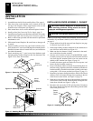
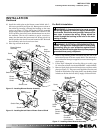
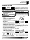
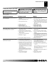
Installing Receiver
1. Disconnect switch wires from the control valve.
2. Remove screws and nuts.
3. Remove switch plate (see Figure 26). Discard after removing.
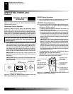
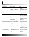
4. Install remote receiver unit onto gas log heater base using clips
(2) and insulating washers provided.
5. Push clips firmly into place (see Figure 27).
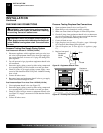
6. Connect wires as shown in Figure 28.
Figure 26 - Switch Plate and Wiring Harness (Switch Plate and
Orientation May Vary Depending On Model)
Wires
Nut
Nut
Screw
Figure 27 - Installing Remote Receiver
Insulating Washers
Mounting
Clips
Figure 28 - Connecting Wires
White Wire
From Receiver
Front
Back
Remote
Receiver
Back
Red Wire From
Receiver
Valve
Front