


Special offers from our partners!

Find Replacement BBQ Parts for 20,308 Models. Repair your BBQ today.

105443-01E
For more information, visit www.desatech.com
For more information, visit www.desatech.com
12
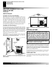
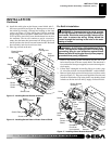
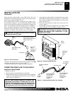
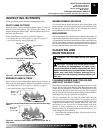
4. A licensed electrician must follow the wiring diagram in Fig-
ure 18 to connect incoming electrical supply to fan kit wiring
harness.
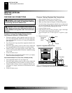
5. Test to make sure the blower is working properly.
6. Reinstall hood assembly (see page 9) and close lower louver door.
7. Place log set back on the unit.
INSTALLATION
Continued
INSTALLATION
Installing Blower Assembly - GA3450T (Cont.)
Connecting To Gas Supply
Figure 18 - Wiring Diagram For Fan Accessory Built-In Installation
If any of the original wire as supplied with the appliance must be
replaced, original replacements must be used. DESA part no.
104015-01 (105°C) for power cord, and DESA part no. 103968-
01 (200°C) for wire harness.
101584-06
120 Vac. 60 Hz. .30 Amps
DESA International, Bowling Green, KY
Red
Red
Fan Switch
(Auto/Off/On)
Blue
Blue
Thermostat
Switch
(N.O.)
Green
White
Green
White
On
110/115
V.A.C.
Blower
Motor
Black
Off
1
2
3
Auto
WARNING: Never attempt to service heater while it is
plugged in, operating, or hot. Burns and electrical shock
could result. Only a qualified service person should ser-
vice or repair heater.
WARNING: Label all wires prior to disconnection
when servicing controls. Wiring errors can cause im-
proper and dangerous operation. Verify proper opera-
tion after servicing.
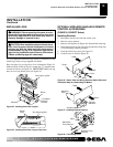
CONNECTING TO GAS SUPPLY
WARNING: A qualified service person must con-
nect fireplace to gas supply. Follow all local codes.
CAUTION: Never connect fireplace directly to the
propane/LP supply. This fireplace requires an exter-
nal regulator (not supplied). Install the external regu-
lator between the fireplace and propane/LP supply.
CAUTION: Use only new, black iron or steel pipe.
Internally-tinned copper tubing may be used in certain
areas. Check your local codes. Use pipe of 1/2" or greater
diameter to allow proper gas volume to fireplace. If pipe
is too small, undue loss of volume will occur.
Installation Items
Before installing fireplace, make sure you have the items listed below.
• piping (check local codes)
• sealant (resistant to propane/LP gas)
• equipment shutoff valve *
• ground joint union
• sediment trap
• tee joint
• pipe wrench
• test gauge connection*
* A CSA design-certified equipment shutoff valve with 1/8" NPT
tap is an acceptable alternative to test gauge connection. Purchase
the optional CSA design-certified equipment shutoff valve from
your dealer. See Accessories, page 31.
IMPORTANT:
Check gas line pressure before connecting fireplace
to gas line. Gas line pressure must be no greater than 14 inches of
water. If gas line pressure is higher, fireplace regulator damage
could occur.
Installation must include an equipment shutoff valve, union, and
plugged 1/8" NPT tap. Locate NPT tap within reach for test gauge
hook up. NPT tap must be upstream from fireplace (see Figure 19,
page 13).
IMPORTANT:
Install equipment shutoff valve in an accessible
location. The equipment shutoff valve is for turning on or shutting
off the gas to the appliance.
Check your building codes for any special requirements for locating
equipment shutoff valve to fireplaces.