


Special offers from our partners!

Find Replacement BBQ Parts for 20,308 Models. Repair your BBQ today.

105443-01E
For more information, visit www.desatech.com
For more information, visit www.desatech.com
11
11
INSTALLATION
Continued
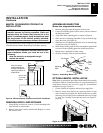
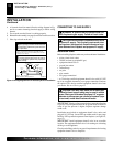
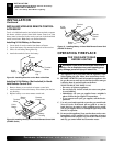
10. Install the switch plate on the blower control shield with 2 -
#10 screws provided (see Figure 16). Route power cord out of
the cabinet by inserting it through the bushing on the outer
casing (see Figure 15). Plug fan kit into 120-Volt grounded
power supply and test operation.
Note:
When switch is in the
AUTO position, the fan will start after the heater has run for a
few moments. The fan will continue to run for several mo-
ments after the heater has been turned off. When switch is in
the ON position, the fan will run until turned to OFF. Reinstall
hood assembly and close lower louver door.
11. Place log set back on the unit.
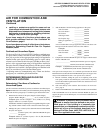
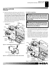
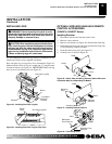
Figure 15 - Installing Blower Bracket Assembly
A
U
T
O
O
F
F
O
N
Wire Harness
Blower Bracket
Assembly
Screw
Power
Cord
Blower
Control
Shield
Shield Cover
Wire
Harness
Switch
Heat
Deflector
Wiring
Routing Hole
Blue
Red
Switch Plate
Blower
Control Shield
Figure 16 - Installing Switch Plate to Blower Control Shield
Switch Plate
Screw
INSTALLATION
Installing Blower Assembly - GA3450T (Cont.)
WARNING: A licensed electrician must connect
the wiring harness to electrical supply following all
local codes. Electrician must provide a clamp on the
box cover to secure the wiring. Wiring should be
routed through the bushing in the hole on the outer
casing of heater.
1. Install a snap bushing found in hardware kit into one of the
holes found on rear of blower control shield. The other hole is
for a strain relief clamp (not supplied) to secure incoming elec-
trical supply.
2. Follow steps 2 through 6 in Installing Blower Assembly, page
10. Also remove black wire from middle/OFF switch terminal.
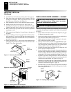
3. Remove black plastic strain relief and power cord from switch
plate (see Figure 17). The power cord supplied will not be used
in built-in installations. Pop in the plastic snap bushing found
in hardware kit into the hole left by supply cord/strain relief.
For Built-In Installation
WARNING: ELECTRICAL GROUNDING INSTRUC-
TIONS This appliance is equipped with a three-prong
(grounding) plug for your protection against shock
hazard and should be plugged directly into a properly
grounded three-prong receptacle.
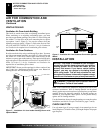
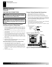
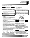
Figure 17 - Installing Blower Bracket Assembly
A
U
T
O
O
FF
ON
Blower Bracket
Assembly
Screw
Wire
Harness
Power
Cord
Blower
Control
Shield
Shield
Cover
Wire
Harness
Switch
Plate
Switch
Clamp
Connector
(not included)
Outlet
Receptacle
Strain
Relief
Blue
Red