


Special offers from our partners!

Find Replacement BBQ Parts for 20,308 Models. Repair your BBQ today.

105443-01E
For more information, visit www.desatech.com
For more information, visit www.desatech.com
10
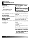
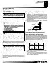
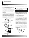
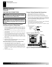
Figure 11 - Removing Hood Screws
Hood
Screen
Rod Cover
Screw
Figure 12 - Removing Hood
Mantel
Screw
Location
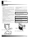
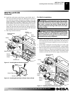
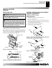
3. Assemble brass trim kit. See Assembling Brass Trim, page 9.
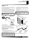
4. Place brass trim on the shoulder screws located on the side
and top of the fireplace. Firmly snap the brass trim over the
shoulder screws on fireplace (see Figure 13).
5. Place mantel base close to wall in desired fireplace location.
6. Install gas line. See Connecting To Gas Supply, page 12
7. Carefully place fireplace on mantel base and center left to right.
Check for gas leaks. See Checking Gas Connections, page 14.
8. Refer to instructions provided with the mantel for permanent
attachment to wall.
9. Slide mantel around fireplace. Be careful not to damage wall
or mantel.
10. Adjust assembly to remove any gaps. From back side of fire-
place, attach two 2" wood screws through base mounting blocks
attached to bottom sides of mantel into base (see instructions
provided with mantel).
11. Attach remaining two 3" wood screws from hardware pack
through openings inside of fireplace sides into the mantel. See
Figure 12, for screw hole location.
INSTALLATION
Continued
Note:
If you are using a mantel with your heater, use the following
instructions. If your heater is built-in, see For Built-In Installation
on page 11.
1. Screen and hood should be removed from fireplace (see page
9). Remove log set and set aside.
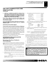
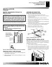
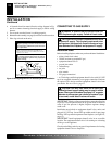
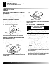
2. Install snap bushings found in hardware kit into both holes in
rear of blower control shield (see Figure 14).
3. Make sure the wire harness is firmly connected to the termi-
nals on the blower bracket assembly.
4. Note the wire locations on back of AUTO/OFF/ON switch.
Carefully remove red wire from the AUTO terminal and blue
wire from the ON terminal. Black wire can remain on the
middle or OFF terminal (see Figure 15, page 11).
5. Carefully disconnect green and white wires from power cord
harness at their insulated connectors.
6. In top of the heater cabinet, locate the four mounting holes on
the outer casing. Align these four holes with those on the blower
bracket assembly. Attach blower bracket assembly to the outer
casing with 4 - #10 screws provided (see Figure 15, page 11).
7. Route the wire harness through the hole to the left side of heat
deflector. Pull wire harness through lower opening to the left
of the blower control shield. (see Figure 15, page 11).
8. Insert the 4 wire harness into one of the round holes in the rear
of the blower control shield and through the rectangular hole
in the front of shield (see Figure 15, page 11).
9. Reconnect red wire to the AUTO switch position. Reconnect
blue wire to the ON switch position. Reconnect green and white
wires to the power cord.
CAUTION: Label all wires prior to disconnection
when servicing controls. Wiring errors can cause
improper and dangerous operation.
CAUTION: Verify proper operation after servicing.
INSTALLING BLOWER ASSEMBLY - GA3450T
Snap
Bushing
Figure 14 - Installing Snap Bushings
Blower
Control
Shield
INSTALLATION
Optional Mantel Installation (Cont.)
Installing Blower Assembly - GA3450T
Figure 13 - Attaching Brass Trim to Fireplace
A
U
T
O
O
F
F
O
N
Shoulder
Screws
Assembled
Brass Trim