


Special offers from our partners!

Find Replacement BBQ Parts for 20,308 Models. Repair your BBQ today.
7
W415-0120 / E / 01.11.05
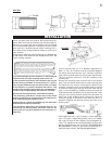
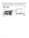
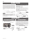
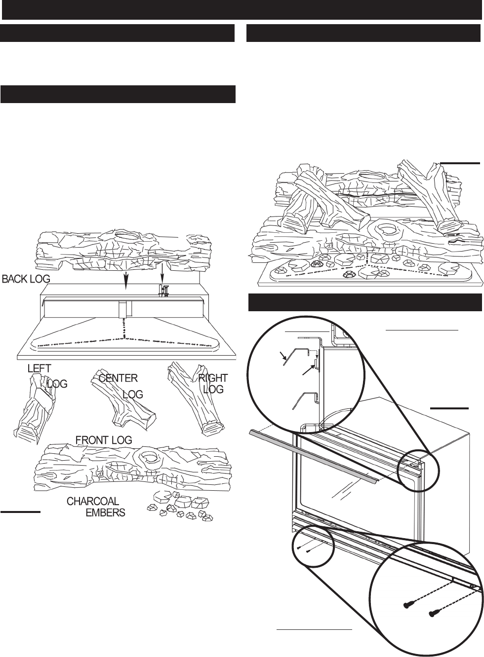
FIGURE 6
To give your insert that authentic masonry fireplace look,
optional fibre firebrick panels are available at your Conti-
nental / Wolf Steel Ltd. dealer. Complete installation and
maintenance instructions are included with the kit.
PHAZER
TM
logs and charcoal embers, exclusive to Conti-
nental Fireplaces, provide a unique and realistic glowing
effect that is different in every installation. Take the time to
carefully position the charcoal embers for a maximum glow-
ing effect.
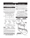
1. Place the front log onto the main burner, pushing it
as close as possible to the burner ports without
blocking/covering them. The left and right spacing between
the log ends and the burner ports should be equal.
YOU MAY FIND IT EASIER TO PLACE SOME CHARCOAL
EMBERS BENEATH THE FRONT LOG NOW.
2. Place the back log onto the step located at the
back of the combustion chamber. The notch situated at the
lower right of the back log should be centered evenly above
the pilot assembly.
3. While supporting the back log, to prevent it from
falling forward, set the three smaller logs into the pockets
and grooves of the front and back logs, respectively.
Log colours may vary. During the initial use of the fireplace,
the colours will become more uniform as colour pigments
burn in during the heat activated curing process.
POSITIONING THE LOGS IMPROP-
ERLY WILL CAUSE FLAME IMPINGE-
MENT AND CARBONING.
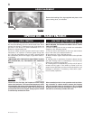
Randomly place the embers beneath the front log, cover-
ing all of the burner area beneath the hollowed out section
of the log. Place the remaining embers along the front.
Keep ember dust away from burner ports to avoid plug-
ging them.
Fine dust found in bottom of bag not to be used.
PHAZER
TM
logs and charcoal embers glow when exposed
to direct flame. Use only certified PHAZER
TM
logs and char-
coal embers available from your Continental / Wolf Steel
Ltd. dealer.
FINISHING
FIBRE FIREBRICK PANELS
LOG PLACEMENT
CHARCOAL EMBERS
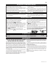
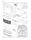
FIGURE 7
UPPER LOUVRES
Insert the back edge of
the upper louvre into the
upper louvre clips.
FLUSH LOUVRE KIT, GI-1L
FIGURE 8
UPPER
LOUVRE
LOUVRE
CLIP
SIDE VIEW
LOWER LOUVRES
Secure the lower louvre
assembly to the insert,
using the 4 screws sup-
plied.