


Special offers from our partners!

Find Replacement BBQ Parts for 20,308 Models. Repair your BBQ today.

6
W415-0120 / E / 01.11.05
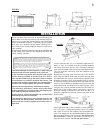
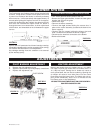
FIGURE 5
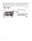
An on/off switch has been included and can be located at
the right side trim. For ease of accessibility, this switch
may be replaced with a wall switch or substituted with a
millivolt thermostat that may be installed in a convenient
location on any wall. Route a 2 strand solid core millivolt
wire through the electrical hole located at the bottom right
side of the unit. The recommended maximum lead length
depends on wire size:
WIRE SIZE MAX. LENGTH
14gauge 100 feet
16gauge 60 feet
18gauge 40 feet
Attach the two leads to terminals 1 and 3 located on the
gas valve.
FIGURE 4
Do not connect the gas valve to electricity (110 volts or
24 volts).
1
2
3
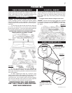
The insert can be equipped with a flashing kit to close off
most fireplace openings. Mount the flashing inside the unit's
outer shell using 4 securing screws. The flashing and trim
are available in many finishes to accent any room decor.
Objects placed in front of the fireplace should be kept a
minimum of 48" away from the front face.