


Special offers from our partners!

Find Replacement BBQ Parts for 20,308 Models. Repair your BBQ today.
5
W415-0120 / E / 01.11.05
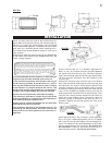
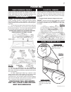
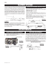
Line the chimney with a 3" or 4" diameter approved liner.
With a 4" liner, an increaser must be connected between
the dilution draft hood and the liner. Chimney installation
must conform to both national and local code requirements.
The liner must be continuous from the fireplace to the
chimney cap.
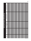
Remove the securing screw from the front of the dilution
plate. Push the dilution draft hood out of the securing clips
and attach the liner using 3 screws equally spaced. Pack
insulation around the liner at the damper area to prevent
air flow from entering the chimney. Move the insert into the
centre of the woodburning fireplace making sure that the
dilution draft hood inserts back into its securing clips. Level
using the four leveling screws located front and back on
either side of the fireplace base. Leveling the insert will
eliminate rocking or excessive noise when the fan is in
operation. Replace the securing screw to the front of the
dilution plate.
FIGURE 2
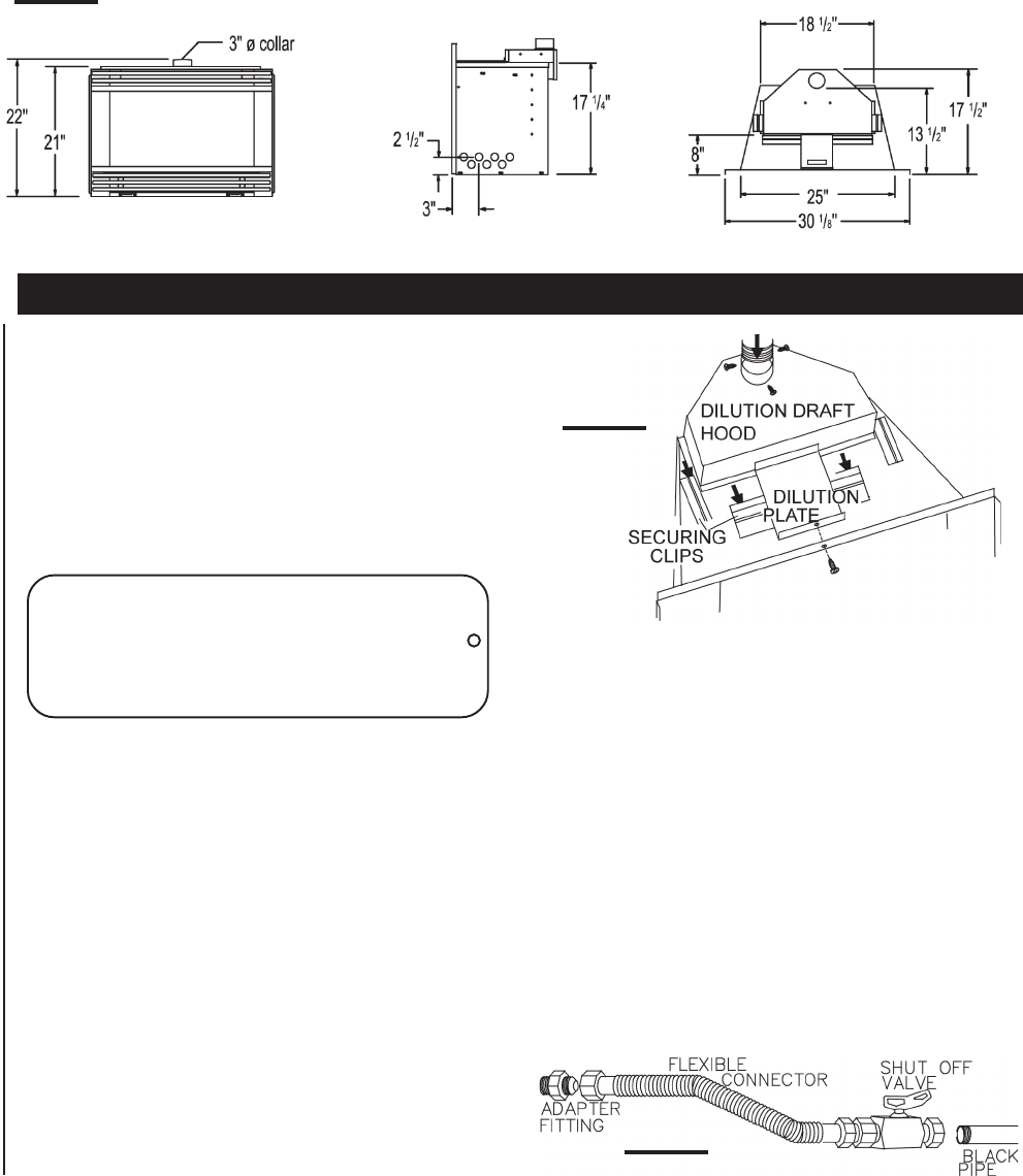
FIGURE 3
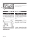
Install rigid black pipe, a flex connector, if local codes per-
mit, or 1/2" type L, copper tubing with a 3/8" to 1/2" adapter
and a shut off valve to the fireplace. Seal and tighten se-
curely. The adapter will be required between the gas valve
and the copper tubing or flex connector. Do not kink flex-
ible connector! Check for gas leaks by brushing on a
soap and water solution. Do not use open flame!
INSTALLATION
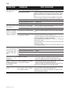
FIGURE 1
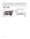
Clean out ashes from the inside of the wood-burning fire-
place. Make sure that the chimney and wood-burning fire-
place are in a clean and sound condition and constructed
of non-combustible materials. If necessary have any repair
work done by a qualified person before installing the in-
sert. Remove the existing fireplace damper or lock into an
open position.
Using screws, attach the fireplace warning tag (W385-0199)
to the inside of the firebox of the fireplace into which the
insert is being installed.
The sheet-metal parts of the fireplace, in which the gas
fireplace insert is to be installed, must not be cut.
If the wood-burning factory-built fireplace has no gas
access hole(s) provided, an access hole of 1½ inch or
less may be drilled through the lower sides or bottom
of the fireplace in a proper workman like manner. This
access hole must be plugged with non-combustible in-
sulation after the gas supply line has been installed.
Ensure that existing chimney cleanouts fit properly.
The refractory, glass doors, screen rails, screen mesh
and log grates may be removed from the fireplace be-
fore installing the gas fireplace insert.
Smoke shelves, shields and baffles may be removed if
attached by mechanical fasteners.
The ventilation openings in the fireplace may be ob-
structed by the backer plates, aluminium trim etc. but
these parts are not to be applied so as to have an air-
tight seal.
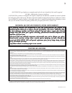
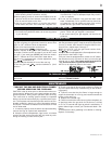
WARNING: THIS FIREPLACE HAS BEEN CONVERTED FOR USE WITH A GAS
FIREPLACE INSERT ONLY AND CANNOT BE USED FOR BURNING WOOD OR SOLID
FUELS UNLESS ALL ORIGINAL PARTS HAVE BEEN REPLACED AND THE FIREPLACE
IS RE-APPROVED BY THE AUTHORITY HAVING JURISDICTION.
ATTENTION: CE FOYER A ETE CONVERTI AFIN D'ETRE UTILISE SEULEMENT COMME
FOYER ENCASTRE AU GAZ ET NE PEUT ETRE UTILSE POUR BRULER DU BOIS OU
TOUT AUTRE COMBUSTIBLE SOLIDE, SANS QUE TOUTES LES PIECES
ORIGINALES AIENT ETE REMPLACEES ET QUE LE FOYER SOIT APPROUVE DE
NOUVEAU PAR LES AUTORITES AYANT JURIDICTION.
W385-0199