


Special offers from our partners!

Find Replacement BBQ Parts for 20,308 Models. Repair your BBQ today.

6
107497
DECORATIVE PATIO FIRE
PROPANE/LP GAS
For more information, visit www.desatech.com
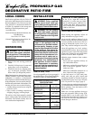
Figure 6 - Equipment Shutoff Valve
ON
POSITION
OFF
POSITION
Open
Equipment
Shutoff Valve
Closed
WARNING: Never use an open
flame to check for a leak. Apply a
mixture of liquid soap and water
to all joints. Bubbles forming show
a leak. Correct all leaks at once.
WARNING: Test all gas pip-
ing and connections for leaks
after installing or servicing. Cor-
rect all leaks at once.
CHECKING GAS
CONNECTIONS
Pressure Testing Gas Supply
Piping System (Fixed Piping
System Only)
Test Pressures In Excess Of 1/2 PSIG
(3.5 kPa)
1. The appliance and its individual shutoff
valve must be disconnected from the
gas supply piping system during any
pressure testing of that system at test
pressures in excess of 1/2 psi (3.5 kPa).
2. Cap off open end of gas pipe where
equipment shutoff valve was connected.
3. Pressurize supply piping system by ei-
ther using compressed air or opening pro-
pane/LP supply tank slowly.
Note:
If not opened slowly, excess-flow
check valve on propane/LP tank will stop
gas flow. If this happens, close propane/
LP supply valve and open again slowly.
4. Check all joints of gas supply piping
system. Apply mixture of liquid soap
and water to gas joints. Bubbles form-
ing show a leak.
5. Correct all leaks at once.
6. Reconnect unit and equipment shutoff
valve to gas supply. Check reconnected
fittings for leaks.
Test Pressures Equal To or Less Than
1/2 PSIG (3.5 kPa)
1. The appliance must be isolated from the
gas supply piping system by closing its
individual equipment shutoff valve dur-
ing any pressure testing of the gas sup-
ply piping system at test pressures equal
to or less than 1/2 psi (3.5 kPa).
CAUTION: Make sure a two
stage external regulator has been
installed between propane sup-
ply and heater. See guidelines
under
Connecting to Gas Sup-
ply
, pages 5 and 6.
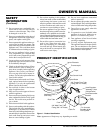
INSTALLATION
Continued
CAUTION: Use only new, black
iron or steel pipe. Internally-tinned
copper tubing may be used in cer-
tain areas. Check your local codes.
Use pipe of 1/2" diameter or greater
to allow proper gas volume to ap-
pliance. If pipe is too small, undue
loss of pressure will occur.
WARNING: Never connect
appliance to private (non-utility)
gas wells. This gas is commonly
known as wellhead gas.
If you are using a 100 lb. supply tank or
larger, and a fixed piping system, installation
must include an equipment shutoff valve,
union, and plugged 1/8" NPT tap. Locate
NPT tap within reach for test gauge hook up.
NPT tap must be upstream from appliance
(see Figure 5).
IMPORTANT:
Install equip-
ment shutoff valve in an accessible location.
The equipment shutoff valve is for turning on
and shutting off the gas to the appliance.
Apply pipe joint sealant lightly to male
threads. This will prevent excess sealant
from going into pipe. Excess sealant in pipe
could result in a clogged burner injector.
Figure 4 - Two Stage External Regulator
with Vent Pointing Down
We recommend that you install a sediment
trap in supply line as shown in Figure 5.
Locate sediment trap where it is within reach
for cleaning. Install in piping system be-
tween fuel supply and patio firepit. Locate
sediment trap where trapped matter is not
likely to freeze. A sediment trap traps mois-
ture and contaminants. This keeps them from
going into appliance controls. If sediment
trap is not installed or is installed wrong,
appliance may not run properly.
CAUTION: Use pipe joint seal-
ant that is resistant to liquid pe-
troleum (LP) gas.
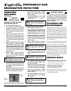
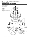
Figure 5 - Gas Connection (When Using
100 lb. Tank or Larger)
* Purchase the optional CSA/AGA design-
certified equipment shutoff valve from your
dealer. See Accessory, page 11.
** Minimum inlet pressure for purpose of
input adjustment.
3" Minimum
Sediment Trap
From Two
Stage External
Regulator (10"
W.C.** to 14.5"
W.C. Pressure)
CSA/AGA Design-
Certified Equipment
Shutoff Valve With
1/8" NPT Tap*
Tee Joint
Pipe Nipple Cap
To
Patio Firepit
Propane/LP
Supply Tank
(100 lb. or
larger)
Two Stage External
Regulator with Vent
Pointing Down
You must install a two stage external regu-
lator. The two stage external regulator will
reduce incoming gas pressure to between 11
and 14 inches of water. If you do not reduce
incoming gas pressure, regulator damage
could occur. Install two stage external regu-
lator with the vent pointing down as shown
in Figure 4. Pointing the vent down protects
it from freezing rain or sleet.