


Special offers from our partners!

Find Replacement BBQ Parts for 20,308 Models. Repair your BBQ today.

12
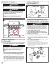
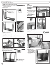
STEP 21
PROPANE CYLINDER SETUP
■ Install Propane Tank Base as shown.
■ Secure the Tank Base to the grill with one self-tapping screw. The hole
location is in the front of the Tank Base Flange.
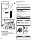
STEP 22
INSTALLING IGNITION BOX
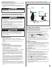
■ Install Rotisserie Motor & Rotisserie Spit as shown.
■ Make sure Rotisserie Motor is placed on the right side of the grill.
NOTE: The Rotisserie Motor will appear to be upside down when installed
correctly.
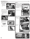
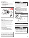
1. Check that the cylinder valve is closed by turning the cylinder
knob clockwise to a full stop.
2. Check that all the grill burner knobs are in the off position.
3. Remove the protective caps from the cylinder valve and
coupling nut.
NOTE: The coupling nut connects to the large outside threads
on the valve outlet.
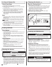
4. Hold the regulator in one hand and insert the nipple into the
valve outlet. Be sure the nipple is centered in the valve outlet.
Hand-tighten the coupling nut, taking care not to cross-thread
the connection (see Fig. 15).
5. Turn the coupling nut clockwise, tighten to a full stop.
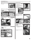
6. Check that the hose has no kinks or sharp bends and clears
areas that will become hot during use. Never put strain on the
hose where it joins a fitting.
NOTE: If you cannot complete the final connection, disconnect
the regulator and repeat steps 4 through 6. If you are still
unable to complete the connection, DO NOT use this valve and
regulator!
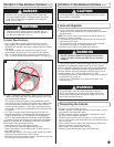
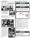
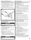
7. BEFORE lighting grill, check all connections for leaks using the
procedure as shown in Fig. 16 on pg. 13.
WARNING
This procedure MUST be performed OUTDOORS only! Be
sure L.P. cylinder valve is closed. Attach to Grill. Read and
follow directions on the cylinder and fuel hose safety tags.
CAUTION
In the connection process, the grill side of the connection will
seal on the back-check in the valve, resulting in a slight resist-
ance. The connection requires about one-half to three-quar-
ters additional turn to complete the connection. To disconnect,
turn counterclockwise. Tighten by hand only. DO NOT use
tools.
DANGER
T
O PREVENT FIRE OR EXPLOSION HAZARD:
• NO SMOKING. DO NOT use or permit sources of ignition
in the area while doing a leak test.
• Perform leak tests outdoors only.
• NEVER perform a leak test with fire or flame.
Connecting Type 1 L.P. Gas Cylinders
Leak Testing
Assembly/Set up
(cont.)
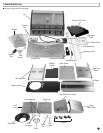
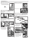
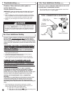
■
Attach the color-coded wires.
■
Attach RED wires from main
burners to terminals A1 and A2.
■
Attach GREEN wires from main
burners to terminals B1 and B2.
■
Attach BLACK wires from main
burners to terminals C1 and C2.
■
Attach BLACK wires from Side
Burner to terminals D1 and D2.
■
Attach LARGE BLACK wires
from Igniter Switch to the pair
of terminals on the left side of
the Ignition Box.
■
Install the 9-Volt battery with
positive (+) terminal as shown
on Ignition Box.
9-Volt Battery
Ignition Box
15
NOTE: The threaded Rotisserie handle is
designed to be removable. When the
Rotisserie is mounted on the grill, the han-
dle will need to be removed to open or
close the lid on the Left Side Burner.
Replace the Rotisserie Handle before
adjusting or removing the Rotisserie.
STEP 20
ROTISSERIE (cont.)
1 Required